This is an old revision of the document!
Table of Contents
Tips & Tricks
General
Here you will find information about general issues concerning the operation of the RepRap Industrial in your specific work environment.
Commandline Access to the linux operating system via SSH
Use SSH on your computer connected to the same LAN as your 3D printer to log in to the RepRap Industrials' built-in BeagleBone Black. You can use the hostname from the printers' Backend-URL and log in with the following access data:
User: kiosk
Password: eight-digit combination from the serial number at the back of the device. Take the first two four-digit blocks - XX-AAAA-BBBB-CCCC-YYYY becomes an "AAAABBBB" password.
Setting a static IP address for RepRap Industrial ethernet connection
First, establish a commandline connection to the printer.
From within the terminal session, edit the network configuration via the command line editor “nano”
sudo nano /etc/network/interfaces
(use the same password as for the SSH connection)
The current DHCP setup looks like:
# The primary network interface
auto eth0
iface eth0 inet dhcp
 pre-up iptables-restore </etc/iptables.rules
Change the setup according to your needs. Example:
  # The primary network interface
  auto eth0
  iface eth0 inet static
  address 192.168.1.20
  netmask 255.255.2555.0
  network 192.468.1.0
  broadcast 192.168.1.255
  gateway 192.168.1.254
  dns-search family.local
  dns-nameservers 192.168.1.254
    pre-up iptables-restore </etc/iptables.rules
The rest of the file remains unchanged. Save the file using CTRL+X and confirm the overwrite query with “Y”. Disconnect and finish by typing
exit
Shut down (see Manual control) and reboot (power-on button, 11 in fig. 4) the RepRap Industrial to establish the alterations.
Use a custom NTP server for time signals
First, establish a commandline connection to the printer.
From within the terminal session, stop the NTP daemon background process
sudo service ntp stop
(use the same password as for the SSH connection)
Edit the NTP daemon configuration via the command line editor “nano”
sudo nano /etc/ntp.conf
Search for the few lines beginning with
server ...
and add an additional new line before these with the address to your local NTP server like this
server 192.168.1.123
add another additional statement anywhere in this file
# ignore panic threshold for huge time differences
tinker panic 0
The rest of the file remains unchanged. Save the file using CTRL+X and confirm the overwrite query with “Y”.
Re-enable NTP client service for background operation
sudo service ntp start
Disconnect and finish by typing
exit
Shut down (see Manual control) and reboot (power-on button, 11 in fig. 4) the RepRap Industrial to establish the alterations.
Changing Shell Password in the BeagleBone Black Operating System
After manually creating a new Micro-SD Card from a pre-packaged upgrade release provided by Kühling&Kühling, the user account running the RepRapOnRails software in the Linux operating system will be in default configuration. To change the password, use SSH on your computer connected to the same LAN as your 3D printer to log in to the BeagleBone Black. You can use the hostname in the printers' Backend-URL as its address and log in with the following access data:
User: kiosk
Password: kiosk
Now you can set a new password by entering
passwd
and following the instructions. In delivery condition the unique password is an eight-digit combination from the serial number at the back of the device. Take the first two four-digit blocks (example: XX-AAAA-BBBB-CCCC-YYYY becomes an “AAAABBBB” password).
Slicing
Any information we gather related to improving or easing the slicing process is listed in the following paragraphs.
Profile display problems in Slic3r for Windows
This bug will be fixed with the upcoming release of SLic3r v1.2.x.
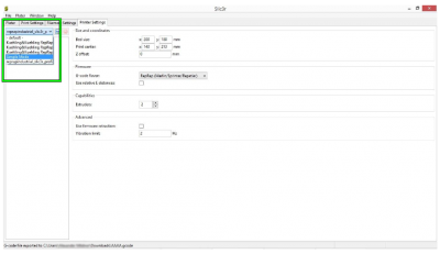
It is a known problem that in Slic3r for Windows the drop-down lists for the profile selection are too narrow to display the full profile name. This can make it impossible to choose the correct profile when processing your slicing settings for creating a G-code.
Try the following to bypass the problem:
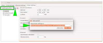
- Select a profile from the drop-down list and click the <save> symbol.
This way, you make the profile name visible and editable.
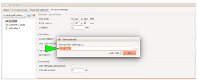
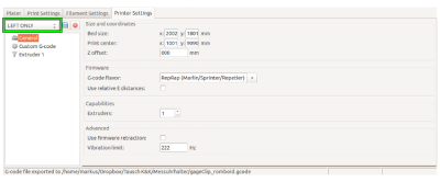
- Delete the current profile name and replace it with a short description, e.g. “LEFT ONLY” instead of “Kuehling&Kuehling RepRap Industrial - LEFT EXTRUDER ONLY”.
Overhang - adjusting the layer thickness
If you want to print filigree objects with overhanging structures without adding supports, try reducing the layer thickness for this print by 15 - 20%. This will result in a finer Z-axis resolution and increased overlay of subsequent layers so that more stability is gained over the height of the target object.
Modifying infill and perimeters
There are currently two Slic3r profiles available at our GitHub repository that provide preset ready-to-print slicing settings. Her are some tips for handling these profiles to adjust them to your needs.
The SOLID profile normally needs no modification since it comes with stable, reliable settings for printing solid objects with 100 % infill.
The ECO profile supplies settings for objects with loosened infill. This makes objects lighter and reduces the print time and the material consumption. To achieve good results, the settings may have to be adjusted.
We recommend to set the following always for printing ECO objects:
- A hull thickness of 1.0 to 1.5 mm. As a rule of thumb divide the hull thickness by the nozzle tip diameter and set the amount of perimeters equal to the result. Such, a closed, smooth and stable hull is ensured.
- Honeycomb infill as it provides highest stability at optimal density.
- A minimum infill of 15 %.
- A maximum infill of 30 %. Increasing the infill further does not have a significant advantage compared to a solid body but strongly increases the printing time.
Operation
In the following you will find more detailed descriptions of functions of the RepRap Industrial. In most cases, these are topics upraised by support requests or in-house lab experiments.
Print bed leveling
The PEI print beds delivered with every RepRap Industrial are custom-made specially to our needs. Due to the manufacturing process, they may show bends and curves which can make handling them a bit tricky. These flaws are accepted due to the superior properties of PEI compared to other subsurfaces when printing ABS. Follow the tips given below and you should have no trouble achieving perfect results.
Of course, the PEI print bed is, like the whole RepRap Industrial, optimized for printing ABS. It also works fine with HIPS, PET-Copolyester, PVA and thermoplastic urethane (TPE-U). Other materials may require a different subsurface, be it another material or a special treatment with tape or glue. Find more information about materials and printing them with a RepRap Industrial in our Knowledgebase.
Accurate leveling is vitally important for the print result. Although correct first layer settings can compensate for slight unevennesses of the print bed, false leveling will ruin a print within the first few layers. Evidence for a leveling mistake can be:
- Asymmetrical layer thickness, especially of the first layer, due to lopsided leveling.
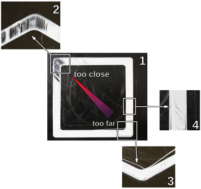
- On one side of the print bed the extruded strand is laid on the print bed instead of being spread → the print bed and the nozzle are too far apart.
- On the other side of the print bed the extruded strand is pressed onto the print bed until the nozzle tip is clogged → the print bed and the nozzle are too close.
- Smearing of the extrusion and possibly clogging of the nozzle due to too closely leveled bed.
- Strands do not stick to the print bed but are being pulled away by the nozzle tip. Of course, this can be due to a wrong bed temperature also – better double-check.
- Extrusion of rounded, unjoined strands.
To avoid such irritations, make use of the following tips:
- Always make sure that the build chamber is adequately and uniformly preheated to at least 90 % of the target temperature (e.g. 63 °C for ABS).
The Z-end stop is temperature sensitive and may cause deviating positioning when exposed to temperature variations.
Keep the build chamber doors as shortly open as possible during leveling to avoid too much heat loss. - If you removed the print bed, always re-insert it in the same direction and orientation it had during leveling.
- Put the print bed with the convex side down onto the print table.
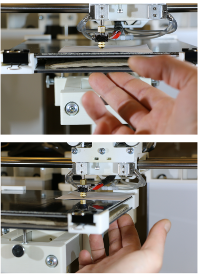
- After adjusting all three leveling points, return the print head to the first position (tap the [Back] button). Check the bed - tip distance by tapping (not pressing) the print bed with a finger next to the nozzle tip: if you see a gap appearing at the slightest touch, the leveling point is correctly adjusted. If even the least pressure is required, the leveling is too high. Repeat this at the other two leveling points. Have a look at the adjacent videos for visual explanation.
- Before waisting time on unsuccessful leveling, please rethink if the currently installed nozzle tip is adequate for the print job. Wider nozzles are more tolerant when it comes to compensating leveling mistakes and may be more suited to the task, especially when printing larger parts.
Tips for easier leveling
If you find it difficult to adjust the three leveling points uniformly with only the spring pressure, place a sheet of paper (not more than standard 80 g/m²) between the nozzle tip and the print bed and carefully push the bed against the tip before fastening the set screws. This way, you ensure a uniform bed - tip distance at all three leveling points.
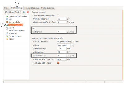
Another way of making leveling a little bit less important is “floating” your print on a raft. Slic3r (and most other slicing software) provides the “raft” function, a special kind of support material, which means that before starting with the actual object a (customizable) number of loosely printed layers is printed to compensate slight leveling mistakes. If you choose the raft settings correctly, beginning with a layer as wide and thick as allowable (depending on the nozzle tip's diameter) leveling will become a much less annoying process.
The raft's first layer is treated as the print's first layer and uses the respective settings. The following layers of the raft are calculated according to the support material settings. Choose the maximal first layer height (Slic3r → Print Settings → Layers and perimeters/First layer height) and a first layer extrusion width of 250 % (Slic3r → Print Settings → Advanced/Extrusion width -First layer) for a compensating, condoning and stable raft.
The raft can either be built of the model's material and cut away later or, if available for the specific plastic, of support material and broken off or dissolved. Check with the Materials' section to see if a secondary support material is available. For break-away or soluble rafts the dual extrusion function of the RepRap Industrial is required. Remember to check that all necessary calibrations and settings have been made as described in the Knowledgebase.
Calibrating the extrusion
The stability and dimensional accuracy of any printed object require a correct amount of filament conveyed through the nozzle. Too little extrusion and the part will be thin-walled, fragile and likely to break. Too much material is likely to clog the nozzle and ruin the print. The amount of material effectively conveyed through the nozzle is depending on:
- the 3D printer itself - slight variations are possible due to the manufacturing process;
- the actual filament diameter - in the range of the dimensional stability of the filament;
- the printed material's properties - the extruder drive wheel grinds deeper into softer materials, thus reducing the actual diameter;
- the idler tension - high tension will cause the drive wheels teeth to grind deeply into the filament, causing a dilation of the material and a reduced output.
To make sure that the print result is stable and accurate, an extrusion multiplier must be found for every material on every apparatus; it may be that this factor must be found for every spool of filament.
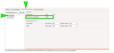
The correct extrusion multiplier is set in the slicing software, compensating for the above named variables.
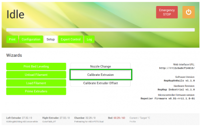
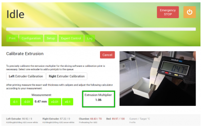
To find the correct multiplier, open the Setup menu at the GUI and choose [Calibrate Extrusion].
A detailed description for ABS filament can be found here.
For other materials, the same procedure applies but you have to prepare a G-code for the test print.
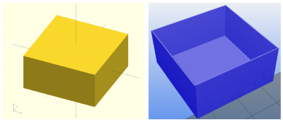
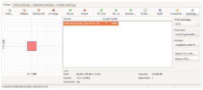
To create a G-code for the extrusion calibration, you need an stl-file of a cube with the dimensions 30x30x15 mm (download here).
Load the stl-file in Slic3r and select the Print Settings tab.
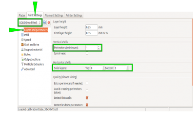
Choose the SOLID profile as a basis.
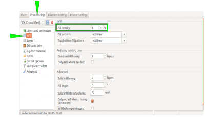
Choose the following settings to make the cube a box without a lid and only one perimeter of 0.5 mm thickness for a wall:
| Layers and Perimeters → Vertical shells Perimeters (minimum) | 1 |
| Layers and Perimeters → Horizontal shells Solid Layers TOP | 0 |
| Layers and Perimeters → Horizontal shells Solid Layers BOTTOM | 3 |
| Infill → Fill density | 0 % |
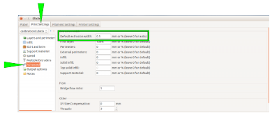
| Advanced → Default extrusion width | 0.5 |
INFO
Saving these settings for Slic3r as an “extruder calibration” profile will make extruder calibration much more comfortable in the future.
Upload the G-code to your 3D printer, print it, measure the wall thicknesses, and calculate the mean value.
Then open the [Calibrate Extrusion] wizard and enter the mean value.
Direct G-code manipulation
The following list contains supported G-code commands that can be used on demand to alter the start and end G-codes in Slic3r or for direct input via the G-code keyboard in the Log menu.
| Command | Effect | Example |
|---|---|---|
G1 | Coordinated Movement X Y Z E | G1 X130 Y85 Z1.75 E4.35 |
G4 S<seconds> | Wait for given duration in seconds | G4 S5 (waits 5 seconds) |
G28 | Home all axes | |
G90 | Use absolute coordinates | |
G91 | Use relative coordinates | |
M80 | Activate build chamber | |
M82 | Set E codes absolute (default) | |
M83 | Set E codes relative while in Absolute Coordinates (G90) mode | |
M104 S<temp> T<extruder> | Set temperature without wait | Adjusting the build chamber temperature, Deactivating the heating elements after end of print job |
M109 S<temp> T<extruder> | Set temperature with wait | |
M140 S<temp> | Set bed target temp without wait | |
M190 S<temp> | Set bed target temp with wait | |
M221 S<extrusion flow multiplier in percent> | Increase/decrease given flow rate | M221 S95 → decrease flow to 95 % of g-code value |
M220 S<print speed multiplier in percent> | Increase/decrease print speed of all drive speeds | M220 S95 → decrease print speed to 95 % of g-code value |
Deactivating the heating elements after end of print job
Sometimes you may want to start a print job just before finishing time or the weekend. Since there is currently no automatic shutdown function, the 3D printer will then stay on all night respectively some days. With the following description you can alter the End G-code of your print so that the heating elements are shut off after the print job has been finished so that the power consumption is reduced significantly. A side effect is, that due to the fact that the build chamber needs some hours to channel off the heat the cooling process is slowed and thereby internal tensions of the printed object are reduced. To deactivate the heating elements after a print job:
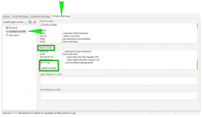
- Open the [Printer Settings] tab in Slic3r and choose the Custom G-code menu.
- Activate the End G-code editor by clicking into the text field.
- Position the cursor in the last line before the
; /END-GCODEentry. - Enter the command
M104 S0 T2
This will set the heating elements of the build chamber to a temperature of 0 °C. - Enter the command
M140 S0
This will deactivate the print bed as the last action of the current G-code.
Adjusting the build chamber temperature
NOTICE
The build chamber temperature is preset to the maximal permissible temperature of +70 °C at delivery.
Exceeding +70 °C will damage interior components of the RepRap Industrial such as stepper motors, bearings and electronics.
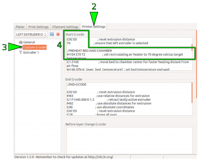
Since hitherto the RepRap Industrial is the only commercially available Open Source 3D printer with an actively heated build chamber, common slicing software does not feature ambient temperature settings. For some materials, it is advantageous to modify the chamber temperature together with the other temperature settings. The build chamber's temperature of the RepRap Industrial is set via the “Start G-code” which can be manually altered.
To change the build chamber temperature (in the following example we use our standard Slic3r - other software may differ in denotations):
- Open your slicing software.
- Open the tab “Printer Settings” and choose “Custom G-code”.
Go to the line reading:
M104 S70 T2; set recirculating air heater to 70 degree celcius target temperature
- Change the entry “Sxy” (here S70) by replacing the value xy with the desired temperature, for example 50° C:
M104 S50 T2; set recirculating air heater to 50 degree celcius target temperature
(for logical reasons, the comment should be aligned)
- If you want to keep the settings, save them in the profile (see Slic3r manual).
Any G-code exported with this profile loaded will heat the build chamber to the stated temperature prior to printing.

