Table of Contents
HT500.2 - Manual
General
Welcome to the HT500.2 3D Printer operating manual of the Kühling&Kühling GmbH (in the following referred to as Kühling&Kühling).
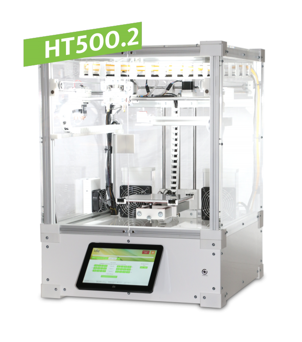
The HT500.2 3D Printer (in the following referred to as HT500.2 or 3D Printer) is a fully automatic stand-alone device for Fused-Filament-Fabrication (FFF) in a lab or commercial environment.
Any information needed for installing and commissioning, operating, troubleshooting, maintenance and repair of the 3D Printer are described in the following paragraphs and the accompanying sites.
This user's manual must be read thoroughly as it is meant to provide the operator with all information needed to operate the HT500.2 safely and reasonably. Please always provide access to the website for any user of the 3D Printer in case of questions or problems.
INFO
The HT500.2 3D Printer is an Open Source project. Any alteration, structural and design changes or customization for test reasons, optimization and improvement are explicitly requested by Kühling&Kühling. We would like to support you with your advancements and are looking forward to receiving your feedback. We will always consider letting your achievements slip in to constantly improve the HT500.2. However, please note that Kühling&Kühling cannot be held liable for damages and injuries resulting from such alterations (see Intended use also).
Valid Version
Hardware revisions
| Number of revision | from | until |
|---|---|---|
| v1.5.x | 11-2016 | current |
On the type plate at the rear side of the HT500.2 you find all information to precisely identify your 3D Printer:
- Serial number
- Date of manufacturing
- Hardware Revision¹
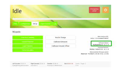
¹ You will also find the valid hardware revision in the [Setup] menu on the touchscreen.
Software versions
Operating sofware:
RepRapOnRails Version v2.x.x → Operating manual
Intended use
The HT500.2 3D Printer has been designed and built for printing three-dimensional workpieces of nearly random geometries from common 2.85 mm thermoplastic filament strands.
The 3D Printer features advanced hot-ends with an extrusion temperature up to 500°C. In combination with the heated build chamber (up to 70°C) and the heated print bed (up to 130°C), this makes the HT500.2 suitable for printing a vast scope of materials. It is therefor capable of performing regular 3D printing tasks with standard thermoplastics as well as special jobs with a variety of technical plastics.
Contact Kühling&Kühling or refer to our website for more detailed information on available and applicable materials.
The HT500.2 is intended for industrial and commercial use. It is not valid for the operation in an explosive atmosphere.
Observing this manual and adhering to the stated information is part of the proper operation.
Improper operation of the HT500.2 can lead to hazardous situations.
It is forbidden to operate the 3D Printer under conditions and for purposes other than stated in this manual.
Operating the HT500.2 is forbidden under the following circumstances:
- The HT500.2 is used for a purpose not designated.
- The HT500.2 or single parts are damaged, the electrical equipment has been installed improperly, or the isolation is defective.
- The HT500.2 does not function flawless.
- Mechanical components or the control system have been inexpertly altered or reconstructed.
- Operating parameter have been altered inadmissibly.
- Operation with unspecified materials.
- Use of unspecified tools.
- Failure to regularly perform the prescribed maintenance work.
- Operation in an explosive atmosphere.
Warranty terms
The general terms and conditions of Kühling&Kühling GmbH apply. The customer is familiar with these terms latest on the day of signing the purchase contract.
The warranty terms and the liability period can be found in the contract documents and in the order confirmation.
Warranty claims and liability are voided in one or more of the following applies:
- unintended usage of the HT500.2
- false setup, commissioning, operation repair or maintenance
- operating the apparatus with defective, missing, improperly installed and/or malfunctioning equipment.
- unauthorized or inadmissible alteration of the electrical or mechanical equipment or the operating parameters of the apparatus.
- use of other than the specified replacement parts, tools, and/or operating materials
- exceeding the specified maintenance intervals
- cases of disaster and force majeure
INFO
Any unintended use or structural alteration of the HT500.2 not agreed upon with and approved in writing by Kühling&Kühling render the warranty and the EU Declaration of Conformity void and free Kühling&Kühling from product liability. Even if approved, alterations have to be carried out by the customer thoroughly and properly. If necessary, adequate safety devices have to be installed.
Ordering wear and spare parts and material
Wear parts must meet the technical specifications defined by Kühling&Kühling. Kühling&Kühling original parts are subject to rigid requirements and meet these standards. A complete list of available wear and spare parts and suppliable materials can be found at our web shop together with an order form.
Life cycle
Find everything you need to know after you ordered your HT500.2 3D Printer in the following paragraphs. From the day of your invoice until the day you want to dispose of the apparatus and anything in between is explained here.
Delivery
The HT500.2 3D Printer arrives at your place fully assembled and can be commissioned directly after setting it up and connecting the power supply.
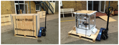
The 3D Printer is delivered in a wooden transport box on a palette. It is advisable to leave the HT500.2 packed and on the palette until moving it to its final installation site for commissioning.
At the installation site, unpack the HT500.2 according to the information in the accompanying Quick Start Guide.
Dispose of the packaging in accordance with the local waste disposal regulations.
After unpacking, inspect the apparatus for:
- damage in transit
- completeness of the delivery (compare delivery note)
If you notice any deviants, please immediately inform the hauler and the manufacturer. Do not put the HT500.2 to use with defective parts.
Transport
To avoid injuries and property damage observe the following notes when transporting the HT500.2:
- The apparatus' weight exceeds 50 kg. Always carry it two by two.
- Keep the HT500.2 horizontal to avoid damaging internal parts.
- Avert shock loads to the housing.
The HT500.2 has been designed for stationary application. It is not equipped with special transport devices such as lifting eyes or handles. The feet provide sufficient clearance to lift the apparatus and carry it to the installation site.
While the HT500.2 is packed and on its transport palette, use a lifting cart or pallet stacker for transportation. Make sure that the weight is evenly distributed and secure the HT500.2 against tilting.
INFO
The housing is not designed for subsequently attaching lifting eyes. If you need to transport the 3D Printer longer ways, load and secure it on a stable pallet and transport it with a pallet stacker or lifting cart.
Detailed information about safeguarding and packing the 3D Printer for shipping can be found in the Service Guide.
Storage
If the HT500.2 must be stored away, choose a leveled storage site and make sure that the 3D Printer does not stand on a ledge.
Before storing it, clean the HT500.2 and protect it from dust with a plastic tarpaulin or air cushion foil.
NOTICE
Do not cover the 3D Printer with a textile sheet since the fibers may enter the supply system and clog the nozzles after recommissioning. Use lint-free plastic sheets only.
The storage ambient conditions for the HT500.2 and its components are stated in the data sheet. For recommissioning after lengthy periods of storage follow the information given in initial commissioning.
Environment, recycling and disposal
When used as intended, the HT500.2 presents no environmental danger.
However, the internal cooling works with a coolant that can be environmentally dangerous when leaking (see data sheet). Please observe the manufacturer's safety data sheet when handling the coolant.
The materials used for printing can also be environmentally dangerous when handled improperly. Always observe the manufacturer's safety data sheet and process plastics only within the limit values specified therein and with respect to the safety instructions.
Generally, consider the environment: the auxiliary and operating materials of the HT500.2 can be dangerous to environment and health.
Awareness and foresighted behavior help avoiding ecological and personnel damage.
Components may bear valuable elements such as rare earths, or may be reusable. Do not waste them by inadequate and thoughtless disposal.
Environmentally hazardous substances must not trickle into the soil or enter the sanitation. They must be stored in suitable containers and be disposed off adequately and in accordance with local and national regulations.
The HT500.2 is recyclable due to its low-pollution equipment. Nonetheless, the European Guideline 2002/96/EG (Waste Electrical and Electronic Equipment - WEEE) and the German Elektro- und Elektronikgesetz (ElektroG) forbid the disposal of the apparatus via the household garbage. For environmental friendly recycling and disposal of the HT500.2 please contact a certified electronic waste management professional.
INFO
Kühling&Kühling emphasize that there is no redemption obligation in this regard.
Personnel safety and device reliability
The HT500.2 features state-of-the-art design and construction and has been built and tested thoroughly so that it is safe and ready to use at delivery. Nonetheless, hazardous situations may appear due to the production process itself and property damage may be caused by false operation.
The risk of experiencing hazardous situations is increased by:
- Using the HT500.2 for other applications than the intended.
- Inappropriate usage of the 3D Printer.
- Operating the 3D Printer in a non-safe state or under improper conditions.
- Insufficient attention, lax handling or intensive soiling.
Therefore:
- Use the HT500.2 for its intended use only.
- The HT500.2 must be in goor working order and in a safe state at any time. Check the apparatus prior to every commissioning and at regular intervals for wear, damage and cleanliness.
- Ensure that nobody can be injured by parts of the 3D Printer.
- Fix any error condition or visible damage immediately. If prompt rectification is impossible, decommission the 3D Printer and do not put it back to use unless all problems have been solved.
- Regard the local accident prevention regulation.
- Provide access to the operating manual for anybody operating the machine.
INFO
The manufacturer cannot be held liable for injuries and damages due to inappropriate usage of the HT500.2.
Inappropriate usage of the HT500.2 voids the manufacturer's warranty.
Injury risks
Some hazards are design related and cannot be avoided by mere constructive measures. To avoid injuries it is necessary that the operator is aware of such situations and takes adequate care. It is the owners responsibility to ensure that every user of the 3D Printer is informed about risks and preventions and that the safety precautions are observed. Access to this manual must be provided at all times.
The safety advice given in the following is meant to protect the operator of the HT500.2.
Electrical safety
The HT500.2 is operated with 110 to 230 V (DC). Touching current-carrying parts can be life-threatening and cause severe injuries.
- Only connect the 3D Printer in accordance with the specifications given in the data sheet.
- Works on the electrical equipment of the HT500.2 and on the power supply system may only be carried out by skilled electricians.
- Always disconnect the 3D Printer from the power supply by switching the main switch off and removing the mains plug from the socket before carrying out maintenance, repair or cleaning.
- Check the condition of cables and isolations at regular intervals and replace damaged parts immediately.
- Do not setup and operate the 3D Printer in a humid environment.
Hot surfaces
Outer surfaces of the HT500.2 are adequately isolated and do not exceed temperatures of +40°C (104°F). They are safe to the touch at any time.
Inside the build chamber, the heating elements generate the necessary ambient temperature for warp-free printing.
Depending on the processed material, surfaces inside the build chamber can reach temperatures up to +70°C (158°F).
The print table is heated separately, also to minimize warpage. It can reach temperatures up to 130°C (266°F).
The extruder nozzles are heated to melt the filament strands and may reach temperatures of 500°C (932°F).
Touching heated components may lead to grade 1 burning injuries, in case of the nozzles of grade 2 of limited size.
To avoid burning injuries:
- Do not open the build chamber during or immediately after completion of a print job.
- Always switch off the preheating and wait until the print bed temperature indicated on the touchscreen has dropped below 50°C (122°F) before removing the print bed. This is also to avoid stress cracks due to sudden temperature drop.
- Some tasks require handling at operating temperature (e.g. changing the nozzle tip). Wear adequate protective gloves when handling hot components.
- Observe the procedures and waiting times stated in this manual.
Coolant
For proper operation the HT500.2 is equipped with a closed loop low-maintenance cooling system that needs little interference. The circuit is filled with coolant type Innovatek Protect IP ready-to-use.
If it is necessary to perform works on the cooling system, such as refilling coolant or exchanging defective hoses, avoid direct skin or eye contact. Always wear adequate protective gloves that are resistant to chemical substances (e.g. PVC, NBR).
Observe the information provided in the manufacturer's safety data sheet.
Additional information concerning the cooling system and required maintenance can be found in the Service Guide.
Noise
The HT500.2 3D Printer is build to be operated in a professional environment such as workshops and laboratories. It is not suited for the operation in an office. During print jobs, it does not exceed 60dB(A), which is considered “inauspicious” for long-term exposure.
Special noise protection equipment is not required.
Fumes
Molten plastics may emit unpleasantly smelling fumes. The HT500.2 3D Printer is equipped with an activated charcoal filter element to reduce such fumes. It is mainly to reduce smells and does not protect from toxic fumes that evaporate from overheated plastics. Such fumes can be perilous.
It is vitally important not to exceed the temperature limits stated for a printed material. Overheating is indicated by discoloration and coking.
Emergency stop
You will find a red Emergency STOP button in the top-right corner of the touchscreen. In case of any unexpected performance of the 3D Printer, press this button to immediately stop any mechanical movement in the build chamber and to shut down all heater elements.
NOTICE
The emergency stop function does not provide a cool down sequence. Do not use the emergency stop button to abort current print jobs, because this may lead to damage of the 3D Printer due to uncontrolled heat accumulation.
Do not use the main switch as an emergency stop button. You risk loosing or corrupting data.
When the emergency stop is triggered, the microcontroller board responsible for the stepper motors, heaters and sensors is reset immediately and returns to idle state afterwards. Now it is safe to resolve any problems or defects in the build chamber.
The build chamber can then be reactivated via the [Print] menue.
Detailed information are provided in the Operating manual.
Operator qualification
Operating and service personnel must be familiar with the information provided in the manual. Special training and qualification are not required for operating the 3D Printer. Works on the electrical equipment and connections of the 3D Printer require profound knowledge of electrics and electronics.
Personal protective equipment
During normal operation it is not necessary to wear special protective gear. Some tasks however should not be performed without taking protective measures. Situations that require protective equipment are specially indicated. It is the owner's obligation to provide adequate protective equipment.
Product reliability
False handling of components can lead to loss of production due to property damage; therefore we strongly recommend following the information given in this manual.
Extruder nozzles
The brazen extruder nozzles are sensitive to heat treatment and mechanical strain.
If the nozzles or extruder barrels are clogged by congealed material, reheating during the normal production flow is utterly sufficient to clear them in most cases.
In case you want to change the material type or clogging is effected by foreign particles (i.e. dust grains dragged along with the filament), it is necessary to remove congealed material from the nozzles. The corresponding description can be found in the cleaning recommendation.
NOTICE
Do not use mechanical tools or open flames to remelt or remove residues in the nozzles. Overheating may induce easing of tensions and deformation. The nozzle is then no longer usable for printing.
Structural and functional description
The following paragraphs name and explain all components of the HT500.2 to give you an exact overview. The terms are used consistently throughout this manual and will help you identifying any part you may wish to find or order as a spare part.
Functional principle
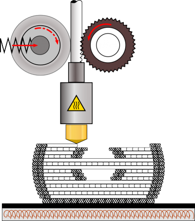
The HT500.2 3D Printer uses the Fused Filament Fabrication (FFF) process to build up workpieces in subsequent layers of 0.10 to 0.60mm thickness. The plastic filament is heated in the nozzle to its melting temperature and continuously conveyed by a cogwheel. The molten plastic is pressed through the bore of the nozzle tip and onto the heated print bed. After each layer the print bed is lowered by the preset layer height and the next layer is applied. The heat of the newly applied plastic ensures an adequate binding of the layers.
All temperatures and movement commands are provided by the GCODE, a file format previously generated with a “slicing” software. This file contains all information for a single print job and is uploaded to the 3D Printer via the web interface. All Kühling&Kühling 3D Printers are built to operate best with Slic3r, an OpenSource Software designed for professional 3D printing.
After the workpiece has been finished the user can leave it in the heated build chamber to slowly cool down thus reducing shrinkage and internal tensions, or he can immediately remove it and start the next print job.
The layered building process enables the user to create even complex forms that otherwise could not be realized.
Hardware components
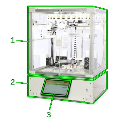
| No. | Description |
|---|---|
| 1 | Build chamber |
| 2 | Electronic chamber |
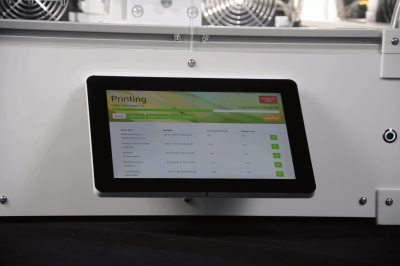
| 3 | Touchscreen |
The HT500.2 is built on an aluminum framework covered with acrylic panels. Its main functional sections are the upper build chamber and the lower electronic chamber. The build chamber is covered with translucent plates to provide insight during production. It contains all mechanical components, the air filter. At the back cover, the filament supply is installed.
The lower is covered with opaque sheets and contains the electronic components and the mains adapter. All connections and the power switches are located here and the touchscreen for operation is mounted at the front cover.
All covers are fixed to the frame with M4x20 hexagon socket screws and hammerhead nuts, thus being easy to remove and making all around access possible to all parts if required.
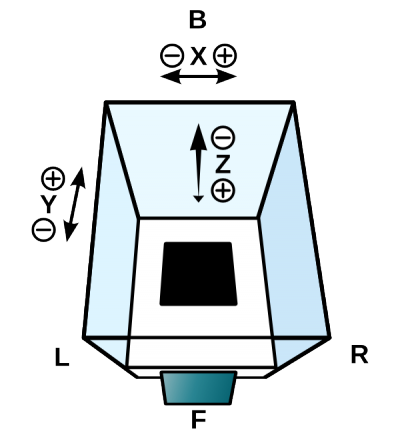
All references concerning directions are defined throughout this manual as follows:
| Tag | Aspect | Description |
|---|---|---|
| F | Front | Standing in front of the 3D Printer's touchscreen and looking inside the build chamber. This is the reference view for all other directions. |
| L | Left | Left side of the 3D Printer, referred to the frontal view. |
| R | Right | Right side of the 3D Printer, referred to the frontal view. |
| B | Back | Backside of the 3D Printer, referred to the frontal view |
All movement directions of the axes are defined throughout this manual as follows:
| Tag | Called | Movement direction |
|---|---|---|
| X⊕ | X positive | Extruder head moves to the right. |
| XΘ | X negative | Extruder head moves to the left. |
| Y⊕ | Y positive | Extruder head moves backwards. |
| YΘ | Y negative | Extruder head moves forward. |
| Z⊕ | Z positive | Print table moves down. |
| ZΘ | Z negative | Print table moves up. |
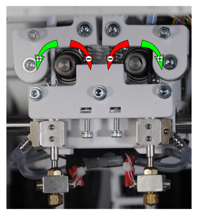
All movements of the extruder drives are defined throughout this manual as follows:
| Tag | Called | Movement direction |
|---|---|---|
| ⊕ | extrude | Left extruder → counter-clockwise rotation Right extruder → clockwise rotation |
| Θ | retract | Left extruder → clockwise rotation Right extruder → counter-clockwise rotation |
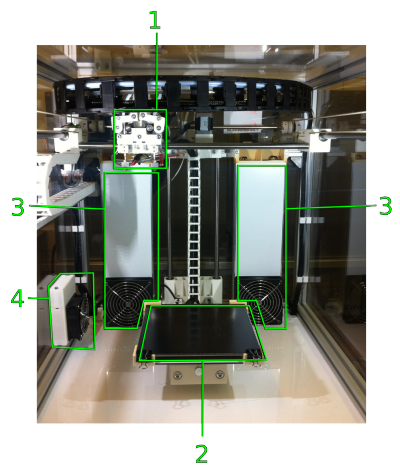
Build chamber
| No. | Description |
|---|---|
| 1 | Extruder head |
| 2 | Print table |
| 3 | Heating elements (covered) and fans |
| 4 | Activated carbon filter with fan |
The build chamber is the main production area with the vertically moving print table and the two-directional horizontally moving extruder head inside.
All electrical motors are installed at their working point and equipped with a water cooling system. The extruder head moves on an H-frame, tooth-belt-driven by two separate stepper motors in X- and Y-direction. The print table is lifted and lowered in Z-direction by a spindle drive.
For regulating the temperature inside the build chamber two heating resistors in separate housings heat the air which then is circulated through the chamber by the fans.
Cables and hoses are installed in and guided by cable carriers.
To minimize air pollution from dissolved substances, an additional fan circulates the air through a filter element filled with granules of activated carbon.
The access to the build chamber is the magnetically closed double door at the front.
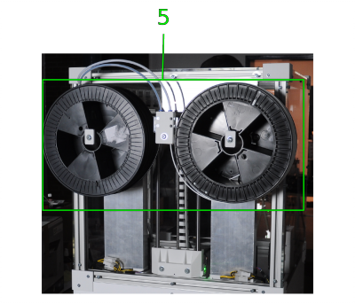
| No. | Description |
|---|---|
| 5 | Filament supply |
The filament spools that provide the necessary material are installed at the rear of the build chamber next to the filament feed unit.
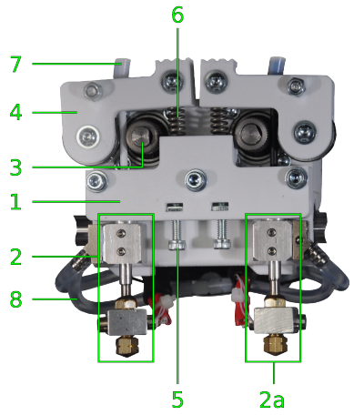
Extruder head components
| No. | Description |
|---|---|
| 1 | Carriage |
| 2 | Left (primary) hot end |
| 2a | Right (secondary) hot end
for dual extruder prints (multi-color or multi-material) |
| 3 | Filament drive gear |
| 4 | Idler lever (release function) |
| 5 | Spring tensioning screw M4x20 |
| 6 | Idler spring |
| 7 | Filament feed hose |
| 8 | Cooling hoses |
The extruder head is mounted to the traverse of the H-frame and moves horizontally in X- and Y-direction with useful operating ranges of X = 200 mm and Y = 185 mm.
It contains the filament drive gears forwarding the filament strands and the hot ends which melt and dose the material onto the print table.
The filament is supplied through a hose from the filament supply and is clamped between the idler lever and the filament drive gear. The filament drive gear is rotated by the filament feed motor and thereby forwarding the filament strand.
Each hot end is provided with its own filament strand, thus enabling bicolored prints, printing two materials or two objects simultaneously or printing with different extrusion thicknesses (e.g. for outer contours and inner filling structures).
The left (primary) hot end is configured for standard single-extruder prints and is the reference nozzle for leveling the print bed. The right hot end is only leveled passively after the print bed has been aligned correctly with the primary hot end.
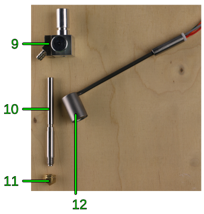
Each hot-end is heated by a ceramic heating cartridge so that the filament is molten inside the nozzle. The integrated thermocouple provides direct alignment of set and actual temperature.
To improve the thermal control of the melting process the hot-end mount is connected to the cooling system, ensuring an even temperature distribution in a well defined area of the nozzles so that there is a preheating zone and a melting zone.
The nozzle is exchangeable to provide different bore diameters for different materials, layer thicknesses or print speed. Ex factory, the 0.35mm tip is preinstalled. Additionally, three nozzles with diameters of 0.25mm, 0.5mm and 0.75mm are included. The tips are distinguishable by the engraved markings.
The 0.35mm and the 0.5mm nozzles should be used for most purposes and can be operated at an extrusion speed of up to
60mm/s. The Slic3r profiles provided by Kühling&Kühling are optimized for the 0.35mm nozzle. Additional information can be found in the Service Guide and in the Slic3r manual.
Please try and find the settings best suited for your task. The Slic3r profiles will be constantly updated and extended.
The 0.75mm nozzle is primarily intended for experimental usage and should only be used with a max. extrusion speed of 20mm/s for a start. Adjust the extrusion speed stepwise until optimized for your needs.
The 0.25mm nozzle is for filigree, thin walled extrusions. Do not exceed an extrusion speed of 35mm/s since the material throughput will not suffice for higher speeds.
Print table and print bed
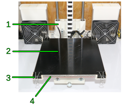
| No. | Description |
|---|---|
| 1 | Elevator assembly |
| 2 | Removable 1.8mm PEI print bed |
| 3 | Bulldog clamp |
| 4 | Heated print table |
The print table is mounted on the crossbeams of the elevator assembly which is positioned accurate to the millimeter in Z-direction in its useful operating range of 280mm by a spindle drive.
The print table itself consists of an aluminum sandwich panel with a silicone rubber heating pad that provides temperatures of up to 130°C, providing an even temperature distribution and ensuring optimal adhesion throughout the printing process.
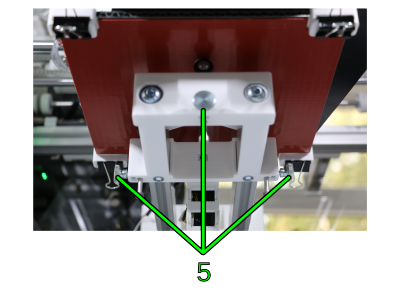
| No. | Description |
|---|---|
| 5 | Set screws of the spring-mounted 3-point leveling support |
It rests on three springs lockable with set screws for an even and accurate leveling since a precisely adjusted distance between print bed and nozzle tip is vital for the print bed adhesion an the print results.
The semi-automated leveling process is described in the Operating Manual. Additional information on leveling can be found in the Knowledgebase.
Print jobs are executed on the removable print bed laid on the print table and fixed with four bulldog clamps at the corners. This fixation allows the use of print beds of different thicknesses.
The print bed can be exchanged for every print, thus minimizing interruption times during production.
The standard print bed included in the delivery is a 210x210x1.8mm polyetherimide (PEI) glass fabric plate that provides excellent adhesion for a large variety of materials, including ABS, Nylon, PET, PC, HIPS, TPU and other.
Important print bed knowledge
The PEI glass fabric composite print beds are, in accordance with the HT500.2's standards, optimized for printing ABS and are custom-made to Kühling&Kühling specifications. Due to the manufacturing process, they may show bends and curves which can make handling them a bit tricky. These flaws are accepted due to the superior properties of PEI compared to other subsurfaces when printing ABS.
It also works fine with HIPS, PET-Copolyester, PVA and thermoplastic urethane (TPE-U). Other materials may require a different subsurface, be it another material or a special treatment with tape or glue.
PEI is highly resistant to a lot of solvents which makes it a suitable subsurface for a lot of materials since removing residues and refurbishing for the next print becomes quite easy.
Find more information about the custom-made Kühling&Kühling PEI print bed:
- Operating and handling are described in the Operating manual.
- Cleaning and care can be found in the Service guide.
- Read about materials and printing subsurfaces in the Knowledgebase.
Drives
| No. | Description |
|---|---|
| 1 | X-axis motor (extruder head motor) |
| 2 | Y-axis motor (H-frame traverse motor) |
| 3 | Z-axis motor (spindle drive of print table) |
| 4 | Filament feed motors (filament gear drive) |
Five electrical stepper motors, one per direction of the extruder head, one for lifting and lowering the print table and one per extruder head nozzle for forwarding the filament, provide all necessary movement for printing. All motors are equipped with water cooling to prevent overheating due to workload and the heating of the build chamber.
Sensors
Sensors for positioning and temperature control are installed inside the build chamber.
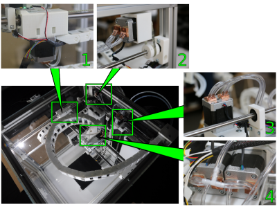
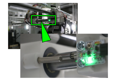
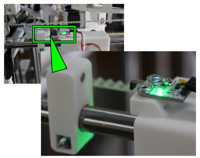
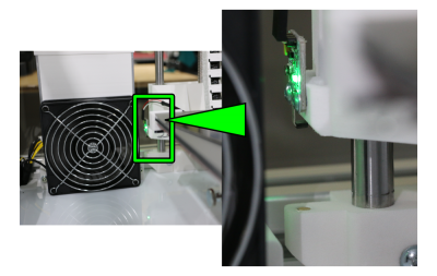
Every axis is equipped with a Hall effect sensor and a magnet for accurate home positioning. If the Hall effect sensor nears the magnet and measures the defined threshold value of the magnetic field strength, the sensor effects a “stop” signal via the microcontroller. After all sensors have given this signal the moving axes are in home position. The home position is the reference value for all relative movement of the extruder head and the print bed.
Thermistors measure the relevant temperatures for the printing process, i.e. the print bed temperature and the build chamber temperature. All thermistors deliver their input signal to the microcontroller and thus effect switching on and off the according heating resistor.
The print bed temperature is measured directly at the heating pad with which it is looped in a control circuit.
The build chamber sensor is installed at the elevator assembly and measures the air temperature inside the build chamber. Its measurements influence the control of the heating resistors inside the heating elements.
The extrusion temperature is measured directly at the heating cartridge by an integrated thermocouple.
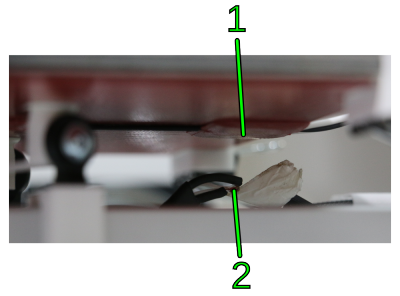
A limit switch is installed at every filament inlet of the filament feed unit
(see below).
Filament supply
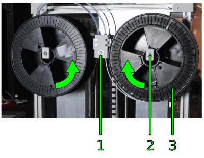
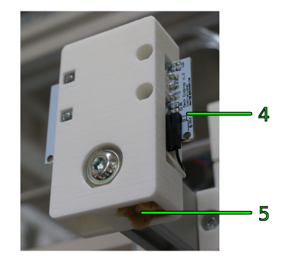
| No. | Description |
|---|---|
| 1 | Feed unit |
| 2 | Filament spool carrier |
| 3 | Filament spool (2.3 kg) |
| 4 | Limit switch |
| 5 | Filament inlet with dust wiping sponge |
The HT500.2 is designed for printing filament strands of a diameter of 2.85 mm with a tolerance of ±0.1 mm. More information about filament and materials can be found in the material section and the print preparation section of the Knowledgebase.
Two separate strands can be fed from the outside to the extruder head. One filament spool can be positioned on each spool carrier; a stop collar prevents them from falling down due to their rotation.
The end of the filament strand is manually inserted into the inlet of the feed unit and led through hoses to the two extruder nozzles. At the inlet the filament is put through a sponge that wipes dust off the strand to keep the material unsoiled before reaching the nozzle.
A limit switch registers the end of the filament strand when the spool is empty. The print process then is interrupted and the lack of material is signaled on the touchscreen. The printing process can be resumed after refilling the supply.
Wiper
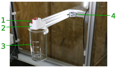
| No. | Description |
|---|---|
| 1 | Wiper lip |
| 2 | Bracket |
| 3 | Excess retainer |
| 4 | Mounting arm |
The HT500.2 3D Printer is equipped with a wiper to enable high-quality dual extruder printing.
During every tool change of a dual-extruder print, the nozzle to be used next will be primed and wiped to ensure pressure loss during its pause time is compensated and the nozzle starts well filled.
Electronic chamber
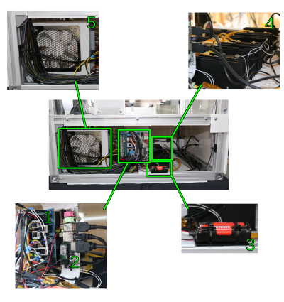
| No. | Description |
|---|---|
| 1 | RADDS v1.5 3D Printer Driver Shield |
| 2 | UDOO Quad Single Board Mini PC |
| 3 | 3V power supply for internal real-time clock |
| 4 | Solid State Relays on cooling substructure |
| 5 | 12V(DC) Mains Adapter |
All control elements are installed in the electronic chamber together with the 12V(DC) mains adapter and the cooling unit.
The chamber is completely covered with white acrylic sheets fastened to the aluminum frame with hexagon socket screws and hammerhead nuts.
The RADDS 3D Printer Driver Shield in conjunction with the SAM3X microcontroller on the UDOO board controls all processes of the printing process, i.e. the drives, the heating resistors, heating fans and the temperature sensors. Exchangeable hardware components are the stepper motor drivers.
The UDOO Quad Single Board Mini PC provides the GUI of the touchscreen and the ethernet connection and processes the G-codes of the slicing software.
Slots in the bottom cover provide an air inlet for the cooling unit.
When the 3D Printer is switched off the internal real-time clock of the Mini PC is fed by two external batteries so that the system's time signal is not lost.
The solid state relays switch the four heating resistors of the build chamber heating and the heating resistor of the print table.
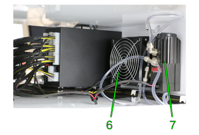
| No. | Description |
|---|---|
| 6 | Cooling unit radiator |
| 7 | Cooling unit pump |
The cooling unit consists of a pump with water reservoir, a radiator and the closed loop coolant circuit filled with an electronic cooling liquid. It is automatically switched on and off when the build chamber is activated/deactivated.
The coolant is pumped in a circle past the motors and the extruder nozzles where it absorbs heat which is then emitted via the radiator.
Check the coolant level monthly and if required, refill as described in the Service Guide.
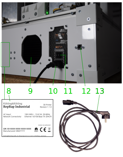
| No. | Description |
|---|---|
| 8 | Type plate |
| 9 | Cooling unit radiator grill |
| 10 | Mains plug |
| 11 | Main switch |
| 12 | RJ45 ethernet plug |
| 13 | 230V supply cable with Schuko plug |
At the rear cover you find the mains plug and the main switch of the mains adapter and the RJ45 ethernet plug for the network connection.
The cooling systems' accumulated warmth is dissipated via the radiator grill to the outside.
The type plate is positioned next to the fixing screws of the cooling water pump.
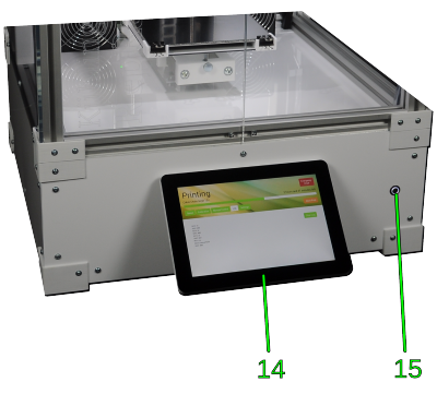
| No. | Description |
|---|---|
| 14 | 10“ TFT high-resolution touchscreen with Graphical User Interface (GUI) |
| 15 | Wake button |
The wake button at the front panel provides a wake-up function and indicates the general operating status of the 3D Printer. It is equipped with a light ring that is illuminated while operational and dims after the 3D Printer has been shut down. Press the button to restart the 3D Printer from standby.
All 3D Printer operation is carried out via the Graphical User Interface at the touchscreen.
Touchscreen operation
Operating the HT500.2 is designed to be comfortable and intuitive. Therefore, a high-resolution 10” TFT touchscreen mounted at the front panel provides an easy-to-use Graphical User Interface (GUI).
All operation of the HT500.2 is carried out via the RepRapOnRails operating software which provides status messages and control functions that can be chosen by simply tapping the respective buttons. Find detailed explanations of functions and operating procedures in the Operating Manual.
In case you experience any trouble, please refer to the Service guide and Troubleshooting. If you cannot solve a problem with the information given there, you are always welcome to contact us personally. We are trying to improve these information constantly and will be grateful for your help when you encounter any previously undescribed faults or problems.
of the operating software is displayed on the right-hand side of Setup menu together with additional system information.
Setup and Installation
Use a lifting carriage to bring the HT500.2 on its transport pallet as near to its setup site as possible. Before setting up the HT500.2 remove the lid and side walls of the transport box and all straps. Subsequently, lift the apparatus off the transport pallet two-by-two and carefully carry it to its final installation location.
Installation requirements
NOTICE
The apparatus must not be set up in a surrounding with high formation of dust (e.g. near woodworks etc.). Ingress of particles into the filament supply system can lead to intense cleaning efforts due to clogging of the nozzles and thus immense non-productive time.
Set up the HT500.2 at a well aerated place with an all-season ambient temperature between 15 and 25°C and a relative humidity of 70%.
Position the HT500.2 on a flat, carrying and enduring surface with a load capacity of at least 75 kg.
To ensure unhindered aeration of the electronic chamber no soft, movable materials (e.g. table cloth, cardboard strips, paper etc.) may be placed underneath the apparatus to prevent clogging of the vent slots.
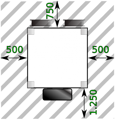
The required setup space must at least be 650 x 650mm and provide approximately 500mm free space to either side to enable unhindered access to the electronic chamber for service and maintenance work.
At least 750mm free space must be left at the back of the HT500.2 to make changing the material easy and to ensure free air circulation at the ventilation grill in the back cover. At the front a free space of 1.250mm is recommended to allow easy operation with open chamber doors.
To easily access the touchscreen in a sitting or standing position the height of the setup table should not undercut 780mm.
A 230V power source must be within the range of the connection cable.
Unpacking the machine
DANGER OF CUTTING INJURIES AND EYE DAMAGE!
The packing straps are pretensioned and may whip when cut, causing cutting injuries or eye damage.
- Hold down the top part of the strap and cut it at the side. Make sure it does not hit somebodies face.
DANGER OF CUTTING INJURIES!
The transport box is made of unfinished plywood and may hold splinters and sharp edges that can cause cutting injuries.
- Take care when removing the transport packaging and wear protective gloves.
NOTE
If the 3D Printer has a temperature below 16°C (e.g. directly after delivery in cold weather) there is a danger of air humidity condensing on sensitive electronic components. This can lead to severe damages due to short circuiting during commissioning.
Therefore, it is necessary to thoroughly let the 3D Printer warm up to ambient temperature for at least 12 hrs. at its operating place prior to commissioning.
Regard the ambient conditions required for operation.
To unpack the machine, cut the tensioning straps of the wooden transport box, remove the lid and carefully lift the box over the printer.
Then cut the tensioning straps around the 3D Printer and remove the wooden cover plate and the air cushion foil.
Set aside and store all parts of the transport packaging for later use, e.g. moving or shipping the 3D Printer.
INFO
Find detailed information on repacking the machine for shipping in the Service Guide.
Removing the transport restraints
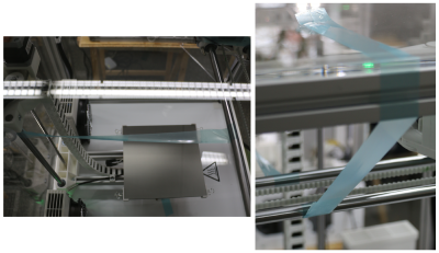
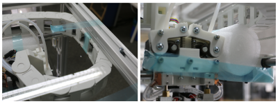
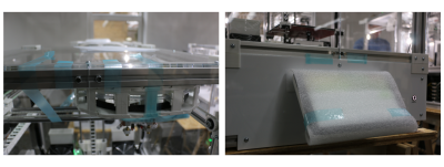
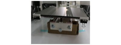
All moving components of the HT500.2 3D Printer are secured with blue tape against damage in transit.
Make sure all transport restraints named in the adjacent pictures have been removed before commissioning the 3D Printer.
Connections
After setting the apparatus up it must be connected to the power supply and the data network.
- Set the power supply main switch at the back of the 3D Printer to <0> (OFF).
- Unpack the supply cable and connect it to the mains plug at the backside.
- Connect the Schuko plug to a 230 V socket.
- Connect the HT500.2 to your data network by plugging the network cable into the RJ45 ethernet plug. Your network must provide DHCP IP address management and should be connected to the internet (to enable the printer to fetch current time signal via Network Time Protocol (ntp)).
Initial commissioning
After set-up has been completed the further commissioning of the HT500.2 takes place at the web interface and the touchscreen as described in the Operating Manual.
Decommissioning
Decommissioning may be necessary on two occasions: the temporary decommissioning if the 3D Printer will just be out of operation for a limited time (e.g. moving) or the permanent decommissioning if the 3D Printer has expired its lifetime and will be scrapped.
Temporary decommissioning
If you need to take the HT500.2 out of operation to move or store it, regard the following information:
- Remove remaining filament from the supply system.
- Clean the 3D Printer, especially the extruder nozzles.
- Move all axes into their home positions.
- Disconnect the mains cable and the network cable. Store them together with the 3D Printer (e.g. fixed with adhesive tape inside the build chamber).
- Protect the print table surface and the touchscreen with a cardboard pad against scratching.
- Secure the extruder head, the print table, and the build chamber doors with strapping tape tape against moving (see Transport).
- Position the 3D Printer on a transport pallet and cover it with a plastic tarpaulin or air cushion foil.
NOTICE
Do not cover the 3D Printer with a textile sheet since the fibers may enter the supply system and clog the nozzles after recommissioning. Use lint-free plastic sheets only.
- Use lashing straps to secure the 3D Printer on the transport pallet.
Permanent decommissioning
If you do not want to use the HT500.2 any longer or if it is damaged beyond repair:
- Take the HT500.2 out of operation as described above.
- Drain the cooling system and collect the coolant. Dispose of the coolant according to your local guidelines and the manufacturer's data sheet.
- Disassemble all components according to their recyclablility and dispose of them adequately and lawfully.
INFO
Components may bear valuable elements such as rare earths, or may be reusable. Do not waste them by inadequate and thoughtless disposal.
On demand maintenance
The HT500.2 3D Printer features a low-maintenance design, thus intensive maintenance time is not required during normal operation. Nonetheless regard the maintenance intervals stated in the Service Guide.
Apart from this, regular cleaning will mostly suffice to keep your 3D Printer running satisfactorily.
In case of faults, refer to the Troubleshooting Guide and the Service Guide where most problems known to us and according remedies are lodged.
INFO
If you encounter and/or solve problems nowhere to be found in the troubleshooting guide, you are welcome to inform us and we will gladly add your experience.
Imprint
Kühling&Kühling GmbH
Christianspries 30
24159 Kiel
Deutschland
E-Mail: office@kuehlingkuehling.de
Tel.: +49 (0) 431 98 35 24 73
Local Court: Amtsgericht Kiel
Commercial Register No.: HRB 17535
Managing Directors: Jonas Kühling, Simon Kühling, Karsten Wenige
VAT Reg.No.: DE305873054

