Table of Contents
Dual extrusion
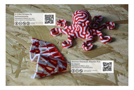
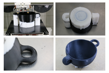
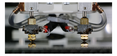
One of the RepRap Industrial 3D-printer's core features is its dual extrusion functionality. Producing visually appealing bicolored or bimaterial parts, making functional parts out of a two-material combination or highly accurate complex geometries with fully attached soluble support structures become possible with the two hot-ends extruder head. And not only is the 3D printer equipped with the necessary hardware but also provides well-engineered software tools to ensure precise alignment of the hot-ends via the common easy-to-use wizards.
Only load the desired combination of materials and perform the required calibrations, then prepare and upload your G-code and you are ready for dual extrusion. All necessary settings that are required for successfully printing with both hot ends are described in the following.
INFO
The descriptions given in the following are only valid for hardware revisions later than rev1.3.0. Users of hardware revisions 1.3.0 and older need to equip their 3D printer with the wiper upgrade kit to participate in the latest developments. The upgrade kit can be ordered pre-assembled with all necessary parts via sales@kuelingkuehling.de.
The dual printing profiles released for Slic3r v1.2.8 (and later) are exclusively configured for the use with the wiper.
Basic dual extruder settings
The steps and settings described in the following paragraphs are valid for all multi-material print jobs. Specific information on printing with soluble support material or bicolored are described in the respective chapters below.
3D printer preparation
Depending on the task, the setup of the 3D printer for dual extruder prints may vary.
Printing bicolored objects will mostly be done with the same resolution requirements throughout the print, so installing the same nozzle diameter on both hot ends is recommended.
For printing support structures with a second material, printing the support with a larger nozzle helps reducing printing time since the printing resolution of the support is not vital for the appearance. Slic3r will calculate interface layers accordingly for nevertheless satisfying results.
Make sure to have installed the nozzle suited to the task on each hot end, and that they are precisely leveled. Compare your setup with your Slic3r settings and adjust these if necessary.
Perform each of the wizards once before the first print. The settings may remain unchanged if no hardware changes (i.e. nozzle or barrel exchange) are made.
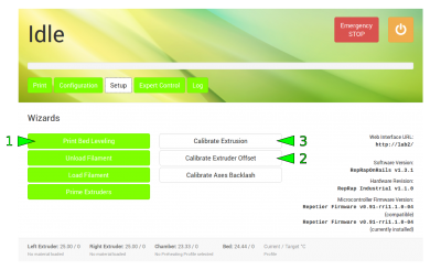
- For dual extruder prints it is vitally important that both hot ends are precisely leveled to the same height. If not yet done, run the [Print Bed Leveling] wizard and follow the on-screen instructions.
- The offset of the hot ends must also be calibrated to ensure accurate relative positioning. Run the [Calibrate Extruder Offset] wizard in the Setup menu of the GUI. Read and enter the values for X and Y offset and [Save] them.
- Do not forget to check the extrusion multiplier for the installed materials and respectively to run the [Calibrate Extrusion] wizard for each hot end if required.
The 3D printer hardware is now ready for dual extrusion.
Wiper check
As previously mentioned, the RepRap Industrial dual extruder function is exclusively designed for the use with a wiper. The Wiper Upgrade Kit is available for 3D printers purchased before July 2015. Hardware revisions later than Rev1.3.0 can be equipped on request with the wiper ex factory.
The following assumes that the wiper has already been installed according to the assembly instructions provided at delivery. If otherwise, find the instructions here.
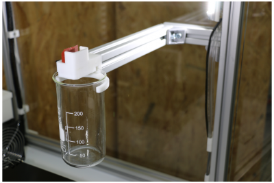
Check that the wiper lip and the nozzle tips are aligned correctly:
- Open the [Expert Control] screen and move the print head to the maintenance position.
- Move the left nozzle 30 mm to the right and 20 mm to the front via the movement control buttons. It should rest directly behind the wiper lip.
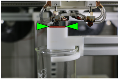
- Make sure the lip's upper rim is aligned in the middle of the nozzle's conical tip (see adjacent picture). Adjust the wiper lip if required.
- Home the print head.
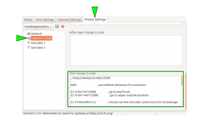
All necessary settings to effect the required movement of the print head into a g-code are implemented in the Tool change G-code in the Custom G-code menu of Slic3r's Printer Settings. It is only filled in when one of the Dual Extruder profiles has been chosen.
Slic3r presets
The full usability of the dual extrusion function is highly depending on the slicing software. As always, Kühling&Kühling recommend using Slic3r which exactly features this demand since the release of version 1.2.8. With the release of this version dual extrusion has become a more reliable, a more usable and a more useful feature especially when it comes to printing soluble support material.
Download your latest Slic3r version here.
The Slic3r-profile at our GitHub repository already come with tested and recommended presets for dual extrusion.
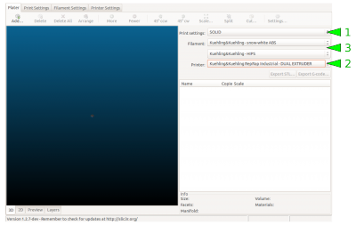
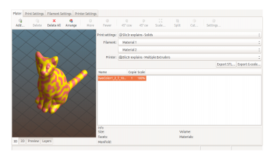
To begin with dual extruder printing the easiest way is to choose the respective preset in in the Plater menu of Slic3r:
- Print settings
for the extrusion, there is no difference between single and dual extruder prints; chooseSOLID,ECOorSOLID (soluble support)according to your needs.
Regard that the extruder nozzles must be assigned correctly. - Printer
from the printer profiles select
DUAL EXTRUDER (bicolored, nozzles 0.35+0.35)
or
DUAL EXTRUDER (soluble support, nozzles 0.35+0.5)according to the task.
After choosing either dual extruder profile a second Filament dropdown menu appears. - Filament
Choose the material type for each extruder individually. The first (upper) material is selected for the left extruder, the second (lower) is selected for the right extruder.
Regard that a second material can only be chosen after dual extrusion has been selected in the Printer dropdown menu.
Additional information on well-functioning combinations of materials can be found in the chapter materials.
Upload your 3D model and adjust all necessary settings as usual.
For supported prints no further manipulation of the 3D model is required.
For bicolored prints additional preparations are necessary.
Printing with soluble support material
Common break-away support is not what takes 3D printing to its limits since its flaws nearly void the possibilities when it comes to surface quality. Due to the necessary gap between support structure and model underside, the later are always subject to gravity and will sag a little, reducing the contact to following layers. To really produce optically impeccable undersides a closely fitting, gapless support is required.
For printing with a soluble support material, it is mandatory that the slicing software provides the possibility of defining the distance between support and model. Only if no gap remains between these two, the superiority of soluble support compared to break-away structures becomes visible in the model.
The following Slic3r presets are provided with the Kühling&Kühling printing profile SOLID (soluble support). This description is meant to give you all necessary information to try out new settings.
Menu “Print Settings”
→ Layers and perimeters
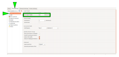
- The
First layer heightmust match the diameter of the support material extruder (the right extruder is preset).
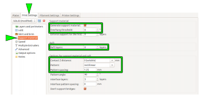
→ Support material
- The checkbox
Generate support materialmust be activated. If required, theOverhang threshold anglecan be adjusted accordingly (check via the Preview in the Plater). - The
Contact Z distancemust be “0 (soluble)” with a (recommended) “rectilinear”Patternand aPattern spacingof 1.25 mm. - It is a good idea to generate 5 - 7
Raftlayers with the support material. Thus, slight leveling mistakes are compensated and an even and reliable subsurface is always provided.
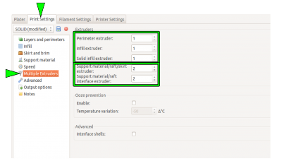
→ Multiple Extruders → Extruders
- Select the model and the support extruder according to the loaded materials.
Preset recommendation:
Perimeter/Infill/Solid infill extruder→Extruder1
Support material/raft/skirt/interface extruder→Extruder2.
Menu “Printer Settings”
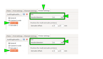
→ Extruder 1 / Extruder 2 → Size
- Check that the correct nozzle size is set for each extruder (remember the First layer height).
Post-treatment of soluble HIPS support
ENVIRONMENTAL DANGER!
d-limonene is very toxic to aquatic organisms and must not enter the sanitation.
Make sure to dispose of d-limonene in a suitable and environmental friendly way.
Regard the manufacturer's safety data sheet when handling d-limonene.
FIRE HAZARD!
d-limonene and its fumes are flammable.
Do not handle in the vicinity of heat, open flames, hot surfaces and other ignition sources.
Do not smoke.
Regard the manufacturer's safety data sheet when handling d-limonene.
DANGER OF INJURY!
d-limonene is a solving agent and therefor must not be handled carelessly.
d-limonene can cause skin and eye irritations.
Wear suitable protective gloves and goggles and regard the manufacturer's safety data sheet when handling d-limonene.
After a complex ABS model has successfully been printed with HIPS soluble support material, the support material must be removed and dissolved. This is an easy process that only requires only a few steps:
- Mechanically break away the easily accessible parts of the support material.
- Place the model in a bath of Kühling&Kühling wash-out solution (97% d-limonene - order directly via sales@kuehlingkuehling.de) so that it is fully submerged. The bath is best stirred, either with a magnetic stirrer or by other means to provide its full solving capacity and to reduce bathing time.
- When all remaining HIPS has been dissolved (check occasionally) remove the model from the bath, briefly dry it with a paper towel, and leave it in a warm and bright place (e.g. windowsill) to dry completely.
Bicolored printing
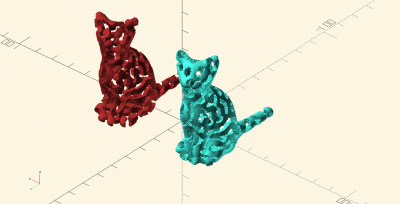
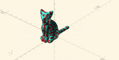
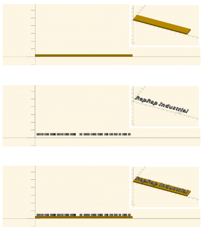
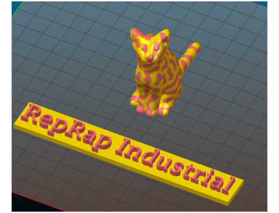
The model preparation for bicolored (and also multi-material) prints is somewhat more complex than supported prints since Slic3r cannot distinguish single areas of a certain model and therefor is not able to automatically calculate the necessary commands. The respective 3D model must be designed as two separate parts with exact relative coordinates to enable Slic3r positioning them as required.
It is best to create the model from two separate parts and join and position them in a common assembly before exporting each as STL, so that the relative positions are recorded in the individual files. Slic3r has the feature to combine multiple STL files into a multi-material print job.
Split the original design into the separate parts within the CAD program, and export each part as STL. Make sure both parts do not intersect.
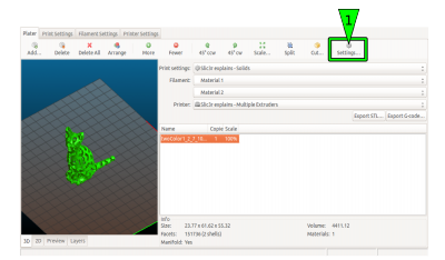
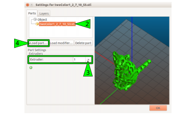
Uploading and slicing the parts:
- Upload the first part to the Plater.
- Open the
Settingsdialog.
- Mark part one and assign it to extruder
1. - Click
Load part …and add the second part from your file system.
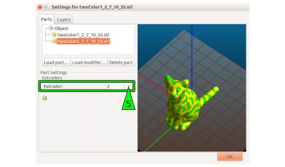
If the single parts are aligned correctly, the preview should now show the exact representation of your desired model.
- Mark the second part and assign to extruder
2. - Close the settings by clicking
OK.
- You can add and load more than one part and modify it as described above.
- Adjust all other necessary settings as usual and as described in Basic dual extruder settings.
- Prepare the 3D printer as described in 3D printer preparation.
Print preparations
The term print preparation summarizes information about:
- Determining material properties
- 3D-suitable construction and slicing
and the like, which may be useful or required prior to printing.
Setting the extrusion temperature
Depending on the material and even with the same but differently colored material the extrusion temperature varies strongly. Most manufacturers provide suggestions for their materials which are always a good idea to start with when printing a new material for the first time.
Fine-tuning the temperature can improve results or reduce unwanted side effects (such as oozing and stringing). Some materials react astonishingly different within a temperature range of ±5 °C. For this reason, beginning with software version v1.1.0, the GUI of the RepRap Industrial is equipped with a direct temperature control and extrude function for quick-and-easy evaluating different temperature settings.
This new feature was installed to give you the opportunity of finding the correct extrusion temperature of any material more directly and comfortably without having to use the [Prime Extruders] wizard.
To find a suitable extrusion temperature:
- Open the Expert Control menu.
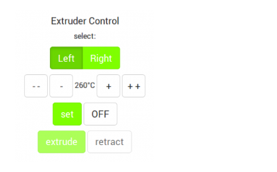
On the right hand side of the screen you will find buttons to choose the extruder (left or right). - Choose an extruder.
After selecting ([Left]/[Right]) the menu is extended. The starting temperature is displayed according to the selected filament profile (see Configuration). - Enter the extrusion temperature recommended by the manufacturer via the touchscreen keyboard. The temperature can be increased or decreased in steps of
10 °C (tap [++] / [- -] once) or 1 °C (tap [+] / [-] once). - Tap [set] when the desired value is set.
The 3D printer will heat to this temperature and then unlock the [extrude] and [retract] buttons. - Tap [extrude] to extrude 5 mm of filament (tapping repeatedly will extrude 5 mm per tap). Tapping [retract] pulls the filament 5 mm back for every tap.
- Watch the extrusion and check whether the following recommendations are visible:
- The filament is extruded smoothly in a single, clean strand.
- No bubbling or discoloration is visible. Bubbling or discoloration mean an extrusion temperature set too high.
If bubbling does not cease after reducing the temperature, this may also mean that the material absorbed moisture. It must then be dried thoroughly. - The extruded strand is not swelling up after leaving the nozzle tip. Upswell means the temperature is too low and the internal friction of the material too high.
- No slipping of the extruder drive gear is visible. Slipping of the drive gear indicates an extrusion temperature set too low and a too high frictional resistance in the nozzle.
The material is not oozing excessively from the nozzle tip after finishing the extrusion and reducing the temperature.
If these points are not met, adjust the temperature and extrude again until the correct appearance is visible.
- Tap [OFF] to deactivate the extruder heating unless you want to keep the current extruder temperature for further steps.
- To verify the settings, print a sample model and check the extrusion properties. Adjust the settings if required.
INFO
Observe that the temperature shown in the footer of the GUI is measured at the hot end heater and may be 5 - 10 °C lower at the nozzle tip. Try increasing the temperature if you are discontented by the printing results.
When extruding new materials do not forget to print a calibration cube to find the correct extrusion multiplier.
When no filament profile is active for the extruder, the starting temperature is set as 180 °C.
INFO
“Normal” oozing is differing largely between materials. Some materials (like ABS) are highly viscous at extrusion temperature and oozing only a little, other materials (e.g. Nylon) are melting in a wide temperature range and are flowing after until the nozzle tip is empty due to their low viscosity. Finding the best extrusion temperature requires some experimenting. Generally it is a good idea to start with the temperature recommended by the manufacturer and steps of 5 °C above and below until the individual requirements are met.
But as much as correct temperature settings the G-code (i.e. the Slic3r settings) influences the print process and the final result. Make sure to use the software and hardware settings suitable for the print job. There is no need to print with an 0.25 mm nozzle tip at low speed when printing large, straight-edged objects.
We ourself are constantly testing new procedures, new materials and new geometries and anything we find out will be shared in the documentation.
Handling 3D files
Any information we gather related to improving or easing the slicing process is listed in the following paragraphs.
Profile display problems in Slic3r for Windows
This bug will be fixed with the upcoming release of SLic3r v1.2.x.
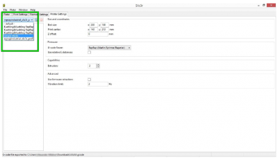
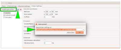
It is a known problem that in Slic3r for Windows the drop-down lists for the profile selection are too narrow to display the full profile name. This can make it impossible to choose the correct profile when processing your slicing settings for creating a G-code.
Try the following to bypass the problem:
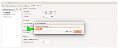
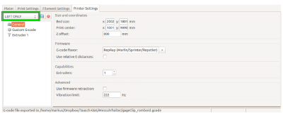
- Select a profile from the drop-down list and click the <save> symbol.
This way, you make the profile name visible and editable.
- Delete the current profile name and replace it with a short description, e.g. “LEFT ONLY” instead of “Kuehling&Kuehling RepRap Industrial - LEFT EXTRUDER ONLY”.
Easy evaluation of STL-files
Especially when using files downloaded from open internet sources it may be that these files are not suitable for printing due to export or modeling mistakes. Misaligned edges (non-manifolds) and holes can render a 3D-model unprintable and make troubleshooting on the 3D-printer an infinite displeasure because no obvious reason can be detected.
One quick and simple way to eliminate this as an error source is checking the suitability of your STL-file for 3D-printing. All you need is a program capable of analyzing the STL-file's mesh.
Slic3r itself can deal with minor troubles and the netfabb company offers a free basic version of their netfabb studio, an STL-handling tool with repair functions. Other tools may be as helpful but these two are used to explain how to recognize a corrupted file.
Slic3r part info:
(see Slic3r manual also)
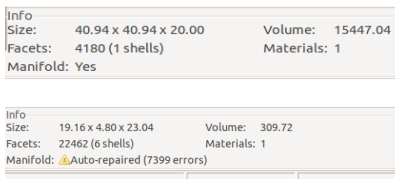
After opening a file in Slic3r, the info box in the bottom-right corner of the plater shows information on the model status. For a single, suitable part the info must look like:
Factes: xxxxx (1 shells)
Manifold: Yes
If it displays Manifold: Auto-repaired (xxxx errors) the file contains degenerations.
It is most likely that it also shows an increased number of shells (e.g. Facets: xxxxx (6 shells) because the part has been split.
Also check the 3D-preview for visible defects. In this case it is better to repair or reconstruct the model.
Regard that the auto-repair function of Sic3r is only suited for repairing minor defects.
Evaluation and repair with netfabb basic:
(see netfabb basic manual also)
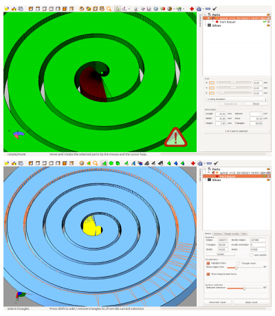
If you open a (supposedly broken) STL in netfabb, the program will display a red warning sign in the bottom-right corner when the part is indeed faulty.
To see mismatches, run the part repair function by clicking on the red cross sign in the toolbar or via the Extras menu. The part is analyzed and all mesh information are displayed, including holes, invalid orientation etc. You can try using the auto-repair function or manually repair defects (very limited in the basic edition) to correct the part prior to newly exporting it as STL.
If simple repair does not lead to satisfactorily results, redesigning or renouncing this specific part and choosing another one may be the best choices.
Overhang - adjusting the layer thickness
If you want to print filigree objects with overhanging structures without adding supports, try reducing the layer thickness for this print by 15 - 20%. This will result in a finer Z-axis resolution and increased overlay of subsequent layers so that more stability is gained over the height of the target object.
Modifying infill and perimeters
There are currently two Slic3r profiles available at our GitHub repository that provide preset ready-to-print slicing settings. Her are some tips for handling these profiles to adjust them to your needs.
The SOLID profile normally needs no modification since it comes with stable, reliable settings for printing solid objects with 100 % infill.
The ECO profile supplies settings for objects with loosened infill. This makes objects lighter and reduces the print time and the material consumption. To achieve good results, the settings may have to be adjusted.
We recommend to set the following always for printing ECO objects:
- A hull thickness of 1.0 to 1.5 mm. As a rule of thumb divide the hull thickness by the nozzle tip diameter and set the amount of perimeters equal to the result. Such, a closed, smooth and stable hull is ensured.
- Honeycomb infill as it provides highest stability at optimal density.
- A minimum infill of 15 %.
- A maximum infill of 30 %. Increasing the infill further does not have a significant advantage compared to a solid body but strongly increases the printing time.
Layers and quality
If it comes to high-quality printing, there is no way to avoid grappling with the “layers” topic. The layer settings influence the quality of a print in the same way as extrusion temperature and movement speed do. In fact, all of these settings interact and influence one another, but you may have recognized that in every slicing software there are a lot of layer-specific settings waiting for adjustment.
The following paragraphs are meant to give you an overview on the topic and further to provide you with detailed information about necessary basic and useful advanced settings to stepwise increase your prints with the RepRap Industrial.
As previously mentioned elsewhere in this manual, we are focused on printing ABS at high quality so the following mostly refers to settings with this material; if otherwise, it will be specially emphasized.
When talking about software settings we always refer to the Slic3r software of Alessandro Ranellucci and his team (http://slic3r.org/).
Everything else only refers to printing with the RepRap Industrial, since this is the basis of our experience. Most things may also be valid for other appliances and different slicing software since it is basic knowledge about FFF manufacturing which can be found elsewhere in books and on the internet. We want to enable the user of a RepRap Industrial to achieve the best possible results with his machine and to provide the necessary knowledge from a single source.
Warping prevention
One of the most important factors deciding whether a print finishes at all and if it does defining the final quality is the adhesion of the first layer to the print bed. The first layer channels off heat tensions from the printed object into the print bed.
ABS, Polycarbonate and Nylon for example are very prone to warping, so only firm adherence to the subsurface can effectively prevent bending and warping. With a first layer not sticking to the subsurface all-over, tensions will manifest all through the model - the object will detach itself from the print bed and the print is wasted. High temperature effected tensions manifest ever stronger with increasing height of the printed model. Long, straight perimeters enhance this effect further.
Three factors determine the adhesion:
- A correctly leveled print bed (explained under Tips & Tricks),
- the material of the print bed and
- the temperature of the print bed.
The material of the print bed must match the chosen filament. The standardized PEI print beds delivered with the RepRap Industrial perfectly match the requirements for printing ABS and HIPS, the most common printing materials for this 3D printer. Other materials such as PET Copolyester and TPE-u also stick to the PEI surface unproblematically.
If a special treatment of the print bed (e.g. PVA glue for printing PVA) or another material (e.g. plywood for printing PA 12) are required, this is specially stated in the list of Materials.
The most necessary print setting apart from the material is the correct print bed temperature to ensure that the filament sticks to its subsurface throughout the printing process. Some materials, like ABS or PC, need high temperatures to stick, whereas for others, such as Nylon or PVA, heat is counter-productive and a cold bed is needed.
The required print bed temperature for any material tested on the RepRap Industrial 3D printer can also be found in the Materials' descriptions.
Other Slic3r settings that help minimizing warping are described in the Tips & Tricks rubric.
The first layer
One thing that always stands out when preparing a print job with the slicing software are the first layer settings. While everything thereafter is only “layers”, the first layer is especially important for the result of any print job.
This is because of the requirements imposed on the first layer:
- Compensation of unevennesses of the subsurface to found an even foundation for the following layers. Slight leveling mistakes, scratches and bends can provide quite an uneven underground; in the slicing profiles provided at our GitHub repository the first layer is preset to be thicker and wider (see below) than the following layers. The increased throughput during printing the first layer fills in waviness of the subsurfaces and thus provides an even underground for the following layers.
- Sticking to the print bed during the entire print job so that heat tensions are channeled off and warping is minimized. The adherence to the print bed is above all responsible for the minimization or manifestation of warpage. Correct first layer settings become the more important the larger the printed object is and the more long, strung-out edges it contains.
- Loosing the adhesion after completion of the print job. After finishing a print job, the model must be detached from the print bed without breaking apart so the first layer must not merge permanently with the print bed but reversible (e.g. due to cooling). This is the only feature that cannot be influenced via the slicing settings and is totally dependent on the material match of printed plastic and print bed.
It has been a challenge to find materials matching the properties of ABS and the above named special features. After a lot of testing, we found that our PEI print bed meets all requirements concerning rigidity, stiffness, flatness, and thermal stability. In combination with the heating of the build chamber we experience no trouble printing straight, non-deforming objects and have had no problems so far removing our models from the print bed.
If you are sure to have leveled your print bed correctly and all temperatures are set right and still you experience delamination and warpage, have a look at your first layer settings; there might be something to be improved here.
Mechanical features for a high-quality first layer
Since the first layer is a well known problem of 3D printing and distinguishes the over-all quality of a 3D Printer, Kühling&Kühling focused on providing a strong mechanical basis from the beginning on.
To make sure that constructive negligence never may ruin a print, intense attention was given to the rigidity of the print table, the choice of an adequate print bed and an easy-to-use and reliable design of the leveling mechanism.
The print table is designed to be stiff and rigid with a precisely manufactured aluminum plate as subsurface for the print bed. The crossbeams have been kept as short as possible to eliminate leverage and the carriage is mounted on high-precision shafts and guided by minimal friction linear slide bearings. The drive spindle allows for extremely precise positioning of the print table in Z-direction with neglectable gravity-compensated backlash.
With the newly designed silicone heating pad of hardware revision 1.1.0, the heat distribution has been improved to be still more even to ensure an over-all heating of the print bed.
The print bed itself is a particularly chosen and tested PEI-glassfibre plate that provides especially good properties for printing ABS. It perfectly spreads the heat provided by the silicone heating pad and, though not thicker than 2 mm, is rigid enough to withstand warping forces as well as sufficiently flexible to remove finished print objects by bending and flexing.
But no constructive measures will suffice if the print bed is askew, so precise leveling is mandatory. To keep the leveling process as time saving as possible, the print table is mounted on a three-point spring support with set screws to fixate it in the correct position. This guarantees the necessary uniform distance of nozzle tip and print surface all over the print bed. The respective leveling instructions are implemented on the touchscreen user interface as a step-by-step wizard that is simple to follow and quick to perform.
First layer settings
As mentioned above, the following recommendations are valid for printing ABS on the RepRap Industrial. We have taken all this into respect when creating our slicing profiles and you do not need to try and find matching settings for the first prints. After growing accustomed to 3D printing and the apparatus' specific features you can start optimizing. Also, if you want to print other materials than ABS, the basic settings named here apply and can be used to modify your results.
The first layer should be thicker and wider than the following layers. In case of the RepRap Industrial we recommend the following (and have already taken it into respect in our slicing profiles):
INFO
The following applies to the nozzle tip size 0.35 mm and the preset Slic3r profiles you installed during initial commissioning. It is meant to give you an overview of the settings relevant for the optimization of the first layer adhesion. Please experiment to find the settings best suited for your task and test all settings before applying them to your final model if you use other nozzle sizes.
When using the 0.5 or the 0.75 mm nozzle tip, there is no further improvement when setting the layer height equal to the nozzle tip diameter. A value of 0.4 mm will suffice for these nozzle tips.
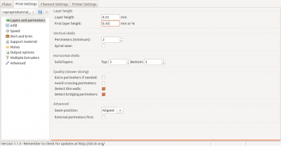
- The first layer height should be adequate to the nozzle tip's diameter.
For example:
Printing with a nozzle tip size 0.35 means setting the first layer height to0.35 mm
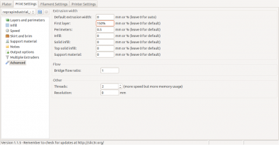
- The extrusion width should be set to
150 %of the first layer height.
For example:
Printing with a nozzle tip size 0.35 and thus 0.35 mm first layer height, setting the first layer extrusion width to150 %means an extrusion width of 0.53 mm. This ensures that enough filament is extruded to compensate for slight unevenness of the subsurface and still enough adhesion.
In Slic3r you can preset and save this setting as a percentage so that the first layer's extrusion width is independent of the actual nozzle tip size.
INFO
Both above mentioned measures compensate for unevennesses of the print bed and increase the tolerance against slight leveling mistakes. The distance between nozzle tip and print bed will assure that the bore is not clogged when passing convex bumps by leaving enough free space in between. The extrusion width will make sure that enough material is conveyed to equalize concave crudities.
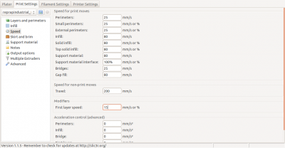
- The first layer speed should be reduced because the print bed does not fuse easily with the material. Slower movement ensures a more even temperature distribution between underground and material and thereby a better binding between them as well as longer cooling time which aids relaxation of tensions.
For ABS, a first layer speed of15 mm/sis a functional value. For other materials, settings from10 to 30 mm/sare recommended (always choose slower values for nozzle tips ≤0.35 mm).
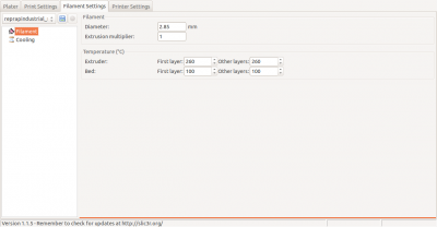
- Changing the extrusion temperature and the print bed temperature can also improve the first layer adherence. Changing the temperature a few degrees may allow for the filament to melt a little more inviscid and to lay more evenly onto the print bed.
Increasing the print bed temperature can have a similar effect as reducing the extrusion speed: a better temperature distribution and increased cooling time.
For printing ABS we find no difference in quality using varying temperatures so the settings are the same for the first and the following layers but this feature may help printing other plastics.
INFO
Optimize the extrusion and print bed temperature for the Material currently installed.
Do not hesitate to try different settings here, since even colored additives may alter the optimal extrusion temperature.
- For filigree or thin-walled objects add a 3 to 6 mm brim and/or 3 to 8 raft layers to increase the effective adhering area (see Slic3r manual also).
- Adding a raft may also compensate leveling mistakes as described here.
These are the settings for the first layer. Try and experiment with them to improve your results or to print new materials. We shall do the same and publish all relevant findings.
Adhesion faults
The fault easiest to diagnose and remedy is the presence of abhesives on the print bed. Recently removed an object from the print bed? Maybe touched the surface? Fingerprints are very effective separating agents that will with certainty prevent sticking of the filament. Any oil, fat, grease or the like will have this effect, so make sure you always clean the print bed with a suitable solvent before starting a new print.
In most cases, false leveling of the print bed is the reason for unsatisfactorily adhesion of the first layer. If the distance between the print bed surface and the nozzle tip becomes to wide, the filament will not be pressed but laid on the surface and single strands will not merge. No cohesion between adjoined strands and no adherence to the underground will develop. It is easy to recognize and as easy to correct such faults as result from false leveling.
Too low a temperature of the print bed also effects poor first layer adhesion. In such cases it might be necessary to find the correct temperature by simply trying. If you cannot succeed with this, something might be wrong with the heating element.
Following layers
Whereas the first layer decides if a print can be finished or not, the following layers influence the fineness and optical appearance of the model. Thinner layers improve the surface quality and chamfers and curvatures are more refined and smooth with much less visible steps. But choosing a lower layer height will also increase the printing time. Regard that halving the layer height more than doubles the print time and at some point the improvement of the appearance will be no longer visible. The other way around you will receive a rougher surface in a shorter time. It is depending on your demands which resolution you try to achieve and how much time you are able or willing to invest for a certain result. The slicing settings are not limited in this regard, so feel free to try it out.
We recommend the following settings when printing ABS or other viscous materials:
- The minimal layer height should not undercut
0.1 mm. For values below this we have no adequate experience since the improvement in surface resolution stands way behind the increase of print time. More inviscid materials may allow even thinner layers.
Regard that the layer height is not necessarily limited by the nozzle tip diameter; it is possible to receive excellent results printing 0.1 mm layers with a 0.35 mm nozzle tip. In the same regard take note that the layer height does not implicitly improve every result. When it comes to fine structures and sharp edges, choosing a smaller nozzle tip without reducing the corresponding layer height can be the key to success. - The maximal layer height should not exceed 80 % of the nozzle tip diameter. Above this value the distance between nozzle tip and previous layer becomes too far and the extruded amount of material may not suffice for good layer binding and thus strong, stable objects.
Slicing software like Slic3r do allow configuring layer heights up to the actual nozzle tip diameter (100%) but broad experience in FFF 3D printing and the Open Source RepRap 3D printer development shows, that max. 80% is a safe approximate value for best results.
Dimensional accuracy
Dimensional accuracy is a core demand of any manufacturing process and therefore is a feature very much looked into in the RepRap Industrial 3D printer. It is built to provide high mechanical accuracy in positioning and supports a variety of possibilities to compensate for mechanical influence factors to improve appearance and dimensional accuracy (e.g. precise backlash calibration).
Also, the recommended slicing software Slic3r calculates extrusion width, material flow and movement to precisely match the dimensions given in the .stl-file.
Kühling&Kühling aim to meet accuracy demands of ±0.2 mm “out-of-the-box”, thus delivering every RepRap Industrial 3D printer carefully adjusted and optimally calibrated.
But some factors that influence the dimensional accuracy of print objects cannot be compensated by the apparatus or the slicing software but can be partly neutralized by slightly altering the model geometry of the CAD-file.
Currently, it is not possible to compensate all influences equally and at the same time but the following tips provide some means to improve the dimensional accuracy of your prints if required.
Influence of thermal expansion
Any material is subject to thermal expansion when heated and shrinkage when cooled. Since the temperature range a plastic passes through during a print is very wide, reaching from around 100 °C at the print bed surface to approx. 20 °C when taken out of the build chamber, the influence of thermal expansion cannot be neglected. Thermoplastics usually have a relatively high thermal expansion factor.
For example: the thermal linear expansion coefficient αL of ABS is approximately 1×10⁻4 K-1, which means that a part of 25 mm length (or diameter) will shrink by approximately:
25 mm x 1×10-4 K-1 x (100 °C - 20 °C) = 0.19 mm (≅ 0.76 %)
due to thermal influences alone.
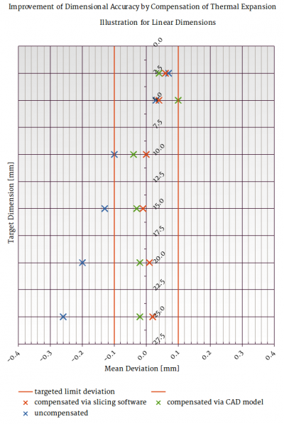
A series of over two hundred measurements with ABS test bodies printed with a RepRap Industrial has shown that the effective deviation lies above the expected value, between 1 and 2%, increasing with decreasing size. Especially for small dimensions ≤5 mm other effects (see below) may counter or intensify the deviation.
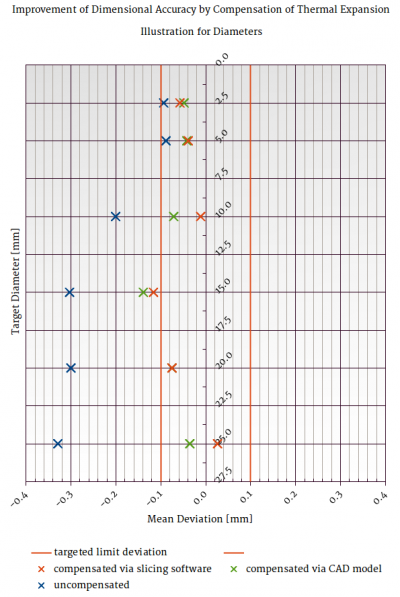
For nominal values between 2.5 and 25 mm, the deviation was measured for uncompensated test bodies and two different methods of compensation.
For the uncompensated measurements the above said applies.
The first and more complicated method of compensation is to directly apply the thermal expansion factor in the 3D CAD model and producing an .stl-file that already comes with corrected dimensions. This is only applicable if the 3D CAD program you are using provides the possibility to multiply all dimensions with a specific factor at once.
This method is advantageous if you want to check dimensions in the CAD-file, which is much more common for .stl-data than ready-sliced g-codes.
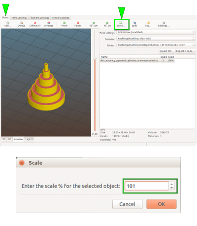
The second, more comfortable way is to directly upscale the model in Slic3r.
For that:
- Upload your .stl-file to Slic3r.
- Choose the [Scale…] button and enter the percental scaling factor.
A factor of 101 % has proven to reduce thermal induced deviation to values between 0.15 and 0.75 % for values ≥5 mm.
Excerpt from the measurement report:
| Nominal value | Mean value (12 measurements) | Deviation | Compensated via 3D CAD model (dim x αL) | Deviation | Compensated via Slic3r (101%) | Deviation | |||
|---|---|---|---|---|---|---|---|---|---|
| [mm] | [mm] | [%] | [mm] | [%] | [mm] | [%] | |||
| 25.00 | 24.74 | 1.04 | 25.05 | 0.19 | 24.99 | 0.03 | |||
| 20.00 | 19.77 | 1.17 | 19.96 | 0.20 | 19.97 | 0.16 | |||
| 15.00 | 14.75 | 1.64 | 14.91 | 0.62 | 14.89 | 0.71 | |||
| 10.00 | 9.84 | 1.65 | 10.03 | 0.30 | 9.97 | 0.27 | |||
| 5.00 | 4.94 | 1.18 | 4.99 | 0.30 | 4.98 | 0.50 | |||
| 2.50 | 2.40 | 4.20 | 2.44 | 2.40 | 2.45 | 1.93 |
The table above outlines that the improvement by either method is significant compared to the uncompensated model while not making much of a difference compared among each other.
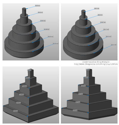
All measurements where done for a set of twelve individually printed test bodies (see adjacent picture). The deviations of each set and diameter where averaged for comparison.
The table also shows that for smallest structures the effect is in fact significant but that other effects need compensating measures too to receive best results.
Influence of backlash
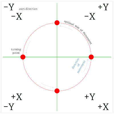
Another factor strongly affecting the dimensional accuracy is the driving unit's backlash, a mechanical characteristic of any device using drive gears, belts and spindle drives to create movement. Whenever the major direction of movements of one of the axes changes and the drive reverses direction, mechanical lash effects a slight offset from the optimal way of movement. This offset, the “backlash”, can be measured and compensated by software means to correct the way of movement whenever necessary.
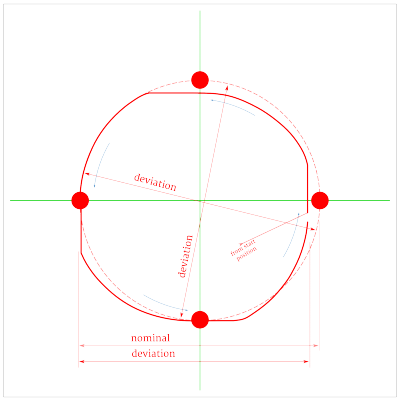
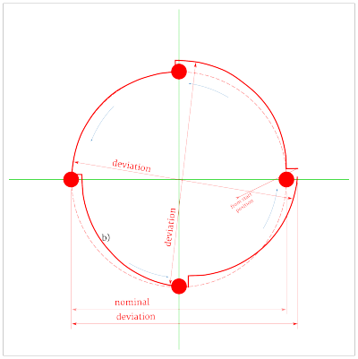
The adjacent pictures exemplarily show the influence of not or incorrectly compensated backlash on the dimensions of a circle, because this is where it is most prominently visible since the direction changes four times.
These figures are based upon a computed simulation with equal settings for the X- and Y-backlash compensation.
For either movement it is assumed that in the starting position (lower left) both belts are fully in the end stop of the pulley.
Regard that over-compensation does not effect a behavior similar to under-compensation, just on the other side, but creates a totally different movement pattern which is not predictable for more complex geometries.
The RepRap Industrial will show slightly different behavior since the axes' drives are differently arranged. The Y-axis almost always needs a higher compensation factor because of the superposition of the two drive belts.
More machine-specific information on behavior and how to measure and compensate the backlash of the RepRap Industrial 3D printer can be found in the Service guide.
Small holes
Small hole dimensions may be subject to two additional error causes apart from shrinkage and print head positioning.
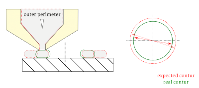
When the print head follows a curve the inner side of an extrusion strand is slightly overfilled which results in an excess of material on the inner wall of a hole.
The effect is strongest in holes of small diameters (< ∅5 mm).
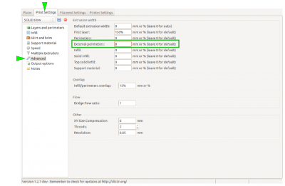
If your print object has little overhanging structures, reducing the outer perimeter extrusion width can help avoiding this effect (see graphic on the right).
But most effectively it is countered directly in the CAD model since it is impossible to calculate and compensate by hardware and slicing software means.
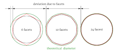
A minor aspect is the number of triangles a model is built from, i.e. the number of facets. Normally, any .stl's resolution is fine enough for sufficiently reflecting the details of a model and respectively loss of accuracy is neglectable.
Still, for small bores the number of facets may play a role if it is very low.
The graphic on the right displays the possible influence of facets on an inner diameter.
In case of roughly faceted objects try increasing the resolution of your CAD model to improve dimensional accuracy.
Filament quality check
Much to our regret, filament manufacturing is not subject to standardization yet. Although we try to provide material of high quality and stable dimensions, manufacturing faults cannot be totally excluded.
If you order filament of other suppliers, please check back that it is within the stated tolerances. Some manufacturers offer a nominal “3 mm” filament which really is 2.85 mm in diameter, while others indeed sell 3.00 mm.
If you note that material purchased via Kühling&Kühling does not meet the standards we set here, please let us know and we will promptly replace the material. We only ask you to send back the flawed material (return note will be included in the new delivery) so that we can discuss the matter with our supplier.
If you experience increased problems with grinding at the drive gear, first thing to check is the quality of the filament currently loaded:
- Is the diameter correct?
- Is the filament round?
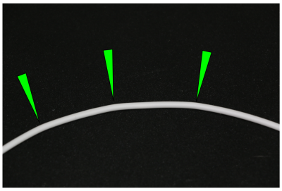
- Is the filament free of bulges and kinks?
INFO
To make sure that there is no problem in the filament feed system, try the following:
• Remove the filament feed hose from the filament inlet (push the blue fixing ring and pull the hose out).
• Feed the filament directly through the hose and try printing.
If the problem remains, check the filament as described.
Refit the hose afterwards!
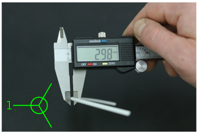
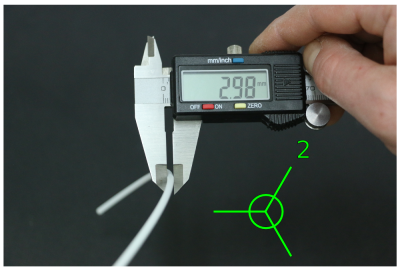
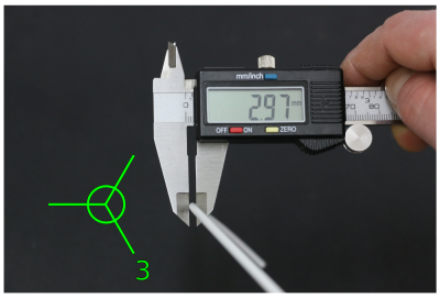
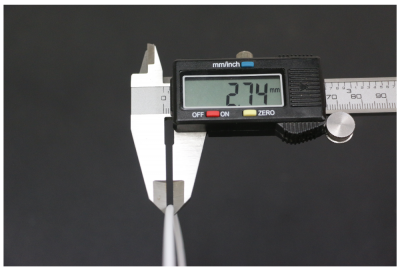
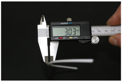
Diameter
Measure the diameter at several points (at least 5 per 0.5 m).
Measure at least twice (best thrice) at each point at an angle of 90° (60°).
The diameter must not deviate from
2.85±0.1 mm (2.75 … 2.95 mm)
A diameter of e.g. 2.98 mm will increase friction in the filament feed system and the nozzle barrel and cause compression and jamming of the filament.
A diameter of 3.00 mm will no longer fit through the filament feed inlet.
Filament below 2.75 mm is, especially when a print job requires a lot of retraction movement, likely to jam the nozzle barrel because molten filament can push itself back up the barrel and form a plug.
Roundness
Measure two times at the same point.
If one diameter deviates from the stated tolerance or if both diameters differ strongly, the filament is out of round and must be replaced.
Out of round filament, even when meeting the admissible values, is likely to form a plug inside the nozzle barrel because molten filament can push itself back up past the main strand.
Calibrating the extrusion
The stability and dimensional accuracy of any printed object require a correct amount of filament conveyed through the nozzle. Too little extrusion and the part will be thin-walled, fragile and likely to break. Too much material is likely to clog the nozzle and ruin the print. The amount of material effectively conveyed through the nozzle is depending on:
- the 3D printer itself - slight variations are possible due to the manufacturing process;
- the actual filament diameter - in the range of the dimensional stability of the filament;
- the printed material's properties - the extruder drive wheel grinds deeper into softer materials, thus reducing the actual diameter;
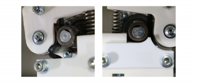
- the idler tension - high tension will cause the drive wheels teeth to grind deeply into the filament, causing a dilation of the material and a reduced output.
To make sure that the print result is stable and accurate, an extrusion multiplier must be found for every material on every apparatus; it may be that this factor must be found for every spool of filament.
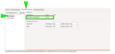
The correct extrusion multiplier is set in the slicing software, compensating for the above named variables.
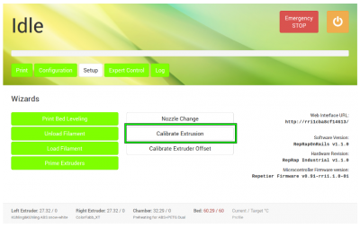
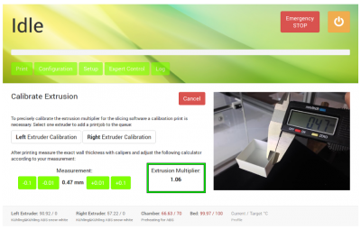
To find the correct multiplier, open the Setup menu at the GUI and choose [Calibrate Extrusion].
A detailed description for ABS filament can be found here.
For other materials, the same procedure applies but you have to prepare a G-code for the test print.
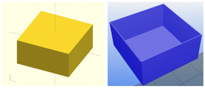
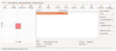
To create a G-code for the extrusion calibration, you need an stl-file of a cube with the dimensions 30x30x15 mm (download here).
Load the stl-file in Slic3r and select the Print Settings tab.
Choose the SOLID profile as a basis.
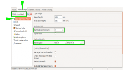
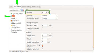
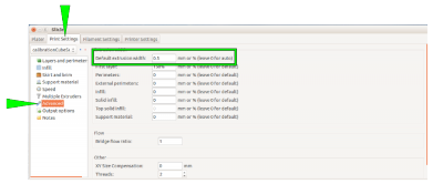
Choose the following settings to make the cube a box without a lid and only one perimeter of 0.5 mm thickness for a wall:
| Layers and Perimeters → Vertical shells Perimeters (minimum) | 1 |
| Layers and Perimeters → Horizontal shells Solid Layers TOP | 0 |
| Layers and Perimeters → Horizontal shells Solid Layers BOTTOM | 3 |
| Infill → Fill density | 0 % |
| Advanced → Default extrusion width | 0.5 |
INFO
Saving these settings as an “extruder calibration” profile will make this calibration much more comfortable in the future.
Upload the G-code to your 3D printer, print it, measure the wall thicknesses, and calculate the mean value.
Then open the [Calibrate Extrusion] wizard and enter the mean value.
Materials
All information given in the following have been thoroughly tested on the RepRap Industrial and are valid for this 3D-printer only.
We guarantee that the stated settings are applicable for the materials provided directly by Kühling&Kühling or manufacturers explicitly named here. Other suppliers are available but since 3D printing filaments are far from being subject to manufacturing standards, Kühling&Kühling cannot be held liable for problems arising from filament obtained from non-specified sources.
Nonetheless we will provide assistance and support for any question concerning the handling/printing of materials. Please also refer to the filament quality check procedure and the respective sections of the service guide as well as the troubleshooting guide if you experience any trouble with your printing material. We are trying to provide information about and remedies for all known problems and are thankful for any hint on new methods, materials and solutions.
Acrylonitrile Butadiene Styrene (ABS)
ABS is a thermoplastic polystyrene copolymerizate of amorphous micro-structure. It is very durable, rigid, tough and impact-resistant in a temperature range of -45°C to +70°C (+80°C for short-term exposure). The chemical resistance at normal ambient temperature is good against caustic solutions, organic acids, alcohols and fats.
ABS finds its uses in the automotive industry, the electrical industry, for toys (e.g the most famous LEGO® brick) and furniture. Covers of kitchenware and office machines as well as body panels in cars and seat shells are often made from ABS. It is the choice material for 3D printed functional parts of excellent dimensional stability, mechanical resilience, and usability as well as meaningful prototypes.
ABS can be assembled by gluing and finished by grinding and sanding as well as painting and varnishing.
The material can be purchased as filament in a wide variety of colors including snow-white and black.
The RepRap Industrial has been built and optimized for printing ABS. The required settings are provided with the material profile Kühling&Kühling ABS snow white installed on the printer at delivery and with the config bundles for Slic3r available at the GitHub repository.
Heating the build chamber is imperative when printing ABS since a uniform temperature distribution throughout the model is one key to minimize warping. If the entire model is kept at a temperature as near to the material's glass transition temperature (Teg) as possible the cooling process can proceed much more evenly. To ensure firm sticking of the first layer, the print bed needs a temperature of at least 100°C.
Printing ABS on the RepRap Industrial
Additional things to know
High Impact Polystyrene (HIPS)
HIPS is polybutadiene rubber-modified polystyrene, a semi-crystalline thermoplastic. It has good impact resistance and dimensional stability and is in its natural (translucent white) state FDA compliant.
HIPS is a low cost material that is easy to machine and fabricate, often used for low strength structural components and finds use in food processing applications, prototyping, toys, housings and covers. It is easy to fabricate, paint and glue.
Since HIPS sticks well to ABS, is thermally tolerant and can be dissolved in a medium that does not affect ABS, it makes for a perfect soluble support material for complicated, interlacing ABS objects. Both materials can be printed together in dual extrusion and with new and upcoming Slic3r developments (keep up to date on http://slic3r.org/), break-away support with all its disadvantages concerning surfaces will soon be a thing of the past.
Printing HIPS on the RepRap Industrial
¹) When printing HIPS solely, the temperatures of print bed and build chamber can be lowered but HIPS withstands the higher temperatures needed for printing ABS which makes it an ideal soluble support material.
Additional things to know
Polyamid (PA, Nylon)
Nylon used in 3D printing is a semi-crystalline thermoplastic of manifold technical uses. PA6 and PA6.6 have become famous in textile fabrication and gave “Nylon” its worldwide reputation. They are both still very important in textile industries.
For 3D printing, PA6 and PA12 are most commonly used. They differ in their mechanical and chemical properties and applications.
PA6 has good dampening and wear characteristics, is thermostable up to +70 °C and impact resistant down to -40 °C. In combination with its high tensile strength it is used for various applications, such as bearings, coatings, housings, guitar strings and surgery suture material, motor parts and others. Its main disadvantage is its strong water absorption (up to 2.6 %) which induces swell and loss of tensile strength.
PA12 is the polyamid with the lowest water absorption (0.7 %) and therefore suitable for constructive parts in humid environment. It is not as strong and thermostable as PA6 (up to +50 °C) but chemically and impact resistant. PA12 is used as packing material in food and pharmaceutical applications, for cable insulation and gas and oil resistant hoses.
All polyamids are warping strongly and require adaptation of the print settings.
PA12
Printing PA12 on a RepRap Industrial
PA12 produces strong and stable prints.
Additional things to know
PA6
Printing PA6 on a RepRap Industrial
| Feature | Setting | see also |
|---|---|---|
| Print bed design | Tufnol with PVA glue | |
| Print bed temperature | 110°C | |
| Build chamber temperature | 70°C | |
| Extruder temperature | 260 to 280°C | |
| Speed settings | Set first layer speed to 2mm/s; following layers can be extruded at standard ABS settings. |
Additional things to know
Polycarbonate (PC)
PC is an amorphous thermoplastic of high strength, impact resistance, rigidity and hardness. Due to the micro-structure, PC is clear and colorless although colorized varieties are available.
It finds its commercial use as a replacement for glass (airplane windows), in optical applications (lenses), for housings and, its most famous application, CDs, DVDs, Blue-Rays. It is most commonly used where other plastics are too damageable.
PC has good insulation properties for electrical currents and is resistant against most mineral acids, oils and fats.
Extruding PC requires high temperatures since it has a high melting temperature and is warping strongly. The print bed must be pretreated with ABS glue.
3D printed PC is strong and stiff. Support material generated from PC is hard to remove due to the excellent layer binding characteristics and object design should regard this.
Printing PC with the RepRap Industrial
*) Dissolve ABS remnants in Acetone until you get a thin, opaque liquid. Apply thinly by dappling the print bed with a soaked cloth.
Additional things to know
Polyethylene terephthalate (PET) Copolyester
PET-Copolyester is a derivate of the thermoplastic PET. It is highly wear and abrasion resistant and chemically resistant to acidic solutions, chlorinated aqueous solutions (e.g. used to sanitize food processing equipment), fuels and fats.
PET-Copolyester is, like PET, commonly used for packagings, bottles and sheets in the food and medical industries as well as for displays and covers.
Printing PET-Copolyester with the RepRap Industrial is quite easy as the material is much less demanding than ABS and can be printed at lower temperatures. It best sticks to the print bed at a temperature of 60°C and requires no build chamber heating at all, although heating does not negatively influence the print (which may be necessary for dual extrusion of different materials).
Warping is not an issue when printing PET-Copolyester. The printed surfaces are of high quality and the objects are dimensionally stable. Uncolored material stays transparent when 3D printed.
PET-Copolyester can be purchased as 3D printing filament under the brand name XT-Coployester directly from the manufacturer ColorFabb in a wide range of colors. It comes with multiple FDA certifications.
Printing PET-Copolyester with the RepRap Industrial
¹ The higher the temperature, the more translucent clear material is extruded.
Additional things to know
Polyvinyl alcohol (PVA)
PVA is a water-soluble synthetic polymer that is used in papermaking, textiles, and a variety of coatings. As 3D printing filament, is has a yellowish clear appearance.
PVA has excellent film forming, emulsifying and adhesive properties. It is also resistant to oil, grease and solvents. It has high tensile strength and flexibility, as well as high oxygen and aroma barrier properties. However these properties are dependent on humidity, in other words, with higher humidity more water is absorbed.
PVA easily absorbs air moisture which leads to an increase in diameter that may cause jamming of the nozzle and affects prints negatively by degassing.
Absorption of water reduces the tensile strength, but increases elongation and tear strength.
INFO
We recommend drying PVA for 2-3 hours at 60°C before printing the first time and store it in a sealed container with drying granulate.
3D printed PVA objects are stiff and brittle, the layer binding is excellent and the warpage minimal. PVA is a useful support material for PETG since both materials can be extrude at equal temperature settings and stick viably together.
Printing PVA with the RepRap Industrial
Additional things to know
| Feature | Setting | see also |
|---|---|---|
| Solvent | Water best solving properties when heated to 30 to 40°C and stirred. | |
| Drying | required; dry at 60°C for 3-4 hrs. | |
| Storage | in closed lid container after drying, preferably with desiccant |
Thermoplastic elastomer (TPE)
TPEs are a group of elastomers suited to be printed with 3D printers. They come in different mixtures, according to the basic substances used. There are polyolefin blends (TPE-o commonly simply called TPE), polyurethan-based TPE-u (or TPU), styrenic block copolymers (TPE-s) and more. They all provide elastic properties and can be used for printing dampers, seals or plugs and a lot of other parts that need elasticity and flexibility.
Printing TPEs cannot be done without some alterations of the RepRap Industrial's standard setup. First thing needed is an adapter (provided for download at Kühling&Kühling GitHub) to bridge the gap between the extruder drive gear and the hot-end inlet otherwise the flexible material will twist and bent. Also, the standard print bed will not suffice and some of the Slic3r settings must be adapted.
Printing TPE with the RepRap Industrial
Additional things to know
| Feature | Setting | see also |
|---|---|---|
| Solvent | None Elastomers do not stick to metal or other plastic surfaces easily and can simply be pulled off for most cleaning purposes. | |
| Warping | low | |
| Drying | not required | |
| Storage | in the open |
Polylactic Acid (PLA)
PLA, a polyester derivate that is due to its molecular structure biodegradable in composting plants, is one of the most common 3D printing material since it is easy-to-use and very rewarding. It is mostly used in 3D printing for visualization of organic forms, such as architectural and landscape models, busts, and decoration. Industrial applications of PLA are found in farming (mulch foils), medical engineering (implants and fixation, seam material), food packaging (yogurt pots), and the textile industry; its UV-resistance, high flashpoint and colorfastness make it useful in a variety of other applications.
The mechanical properties of PLA are near those of Polystyrene (PS) but with a lower glass transition and continuous operation temperature (45 - 65 °C), which makes it unusable for exposition to heat (e.g. coffee mugs).
PLA is available from a lot of manufacturers in a variety of colors and different fillers (e.g. wood or bronze fill), which makes it easily available, relatively cheap and suitable for many visualization applications. Due to the high availability it is not part of the Kühling&Kühling product range.
Printing PLA with the RepRap Industrial
| Feature | Setting | see also |
|---|---|---|
| Print bed design | standard PEI print bed, glass, BuildTak | |
| Print bed temperature | OFF-50°C | |
| Build chamber temperature | OFF°C | |
| Extruder temperature | 180-220°C * | |
| Speed settings | reduce standard settings for ABS by 20% * Perimeters: 20mm/s Infill: 24mm/s | |
| Idler lever preload | 4.0mm | |
| Nozzle tip | all |
* depending on color, filler; test to find best suitable settings for your application.
For example: colorFabb's famous woodfill is best extruded at 225 °C with 12 mm/s for perimeters and 24 mm/s for the infill.
Additional things to know
| Feature | Setting | see also |
|---|---|---|
| Solvent | Tetrahydrofuran
USE RESPONSIBLY! | |
| Layer binding | good | |
| Part strength/stability | medium; parts are stiff and brittle | |
| Warping | low | |
| Drying | not required | |
| Storage | in the open | |
High-temperature materials
For extruding the materials described in the following temperatures above 300°C are required. For 3D printing them on a RepRap Industrial this means that the (optional) high-temperature hot-end is required, which allows for extrusion temperatures of up to 400°C.
Polyether ether ketone (PEEK)
PEEK is a semi-crystalline high performance thermoplast resembling Polyoxymethylene (POM) or PET but with better mechanical properties and temperature stability. Also, it features a high solidity, stiffness, chemical and radiation resistance, high flaming point and good sliding and wear properties.
Due to its superior properties, the material is very expensive, which often makes it second choice behind POM or similar.
PEEK is typically used for bearings, thrust washers, gear wheels, gaskets and pumps.
Printing PEEK on a RepRap Industrial
Additional information
| Feature | Setting | see also |
|---|---|---|
| Warping | low | |
| Stringing | little to none | |
| Drying | not required | |
| Storage | in the open | |
| Tempering | can be useful for very stiff material that keeps uncoiling; heat at 200°C for 1-2 hrs. | |
| FDA and EMA compliant |
Tips & Tricks
Here you will find information about issues concerning the operation of the RepRap Industrial in your specific work environment or solutions for questions that have been upraised by support requests.
Commandline Access to the linux operating system via SSH
Use SSH on your computer connected to the same LAN as your 3D printer to log in to the RepRap Industrials' built-in BeagleBone Black. You can use the hostname from the printers' Backend-URL and log in with the following access data:
User: kiosk
Password: eight-digit combination from the serial number at the back of the device. Take the first two four-digit blocks - XX-AAAA-BBBB-CCCC-YYYY becomes an "AAAABBBB" password.
Setting a static IP address for RepRap Industrial ethernet connection
First, establish a commandline connection to the printer.
From within the terminal session, edit the network configuration via the command line editor “nano”
sudo nano /etc/network/interfaces
(use the same password as for the SSH connection)
The current DHCP setup looks like:
# The primary network interface
auto eth0
iface eth0 inet dhcp
 pre-up iptables-restore </etc/iptables.rules
Change the setup according to your needs. Example:
  # The primary network interface
  auto eth0
  iface eth0 inet static
  address 192.168.1.20
  netmask 255.255.255.0
  broadcast 192.168.1.255
  gateway 192.168.1.1
  dns-search family.local
  dns-nameservers 192.168.1.1
    pre-up iptables-restore </etc/iptables.rules
The rest of the file remains unchanged. Save the file using CTRL+X and confirm the overwrite query with “Y”. Disconnect and finish by typing
exit
Shut down and reboot the RepRap Industrial to establish the alterations.
Use a custom NTP server for time signals
First, establish a commandline connection to the printer.
From within the terminal session, stop the NTP daemon background process
sudo service ntp stop
(use the same password as for the SSH connection)
Edit the NTP daemon configuration via the command line editor “nano”
sudo nano /etc/ntp.conf
Search for the few lines beginning with
server ...
and add an additional new line before these with the address to your local NTP server like this
server 192.168.1.123
add another additional statement anywhere in this file
# ignore panic threshold for huge time differences
tinker panic 0
The rest of the file remains unchanged. Save the file using CTRL+X and confirm the overwrite query with “Y”.
Re-enable NTP client service for background operation
sudo service ntp start
Disconnect and finish by typing
exit
Shut down and reboot the RepRap Industrial to establish the alterations.
Changing Shell Password in the BeagleBone Black Operating System
After manually creating a new Micro-SD Card from a pre-packaged upgrade release provided by Kühling&Kühling, the user account running the RepRapOnRails software in the Linux operating system will be in default configuration. To change the password, use SSH on your computer connected to the same LAN as your 3D printer to log in to the BeagleBone Black. You can use the hostname in the printers' Backend-URL as its address and log in with the following access data:
User: kiosk
Password: kiosk
Now you can set a new password by entering
passwd
and following the instructions. In delivery condition the unique password is an eight-digit combination from the serial number at the back of the device. Take the first two four-digit blocks (example: XX-AAAA-BBBB-CCCC-YYYY becomes an “AAAABBBB” password).
Print bed leveling
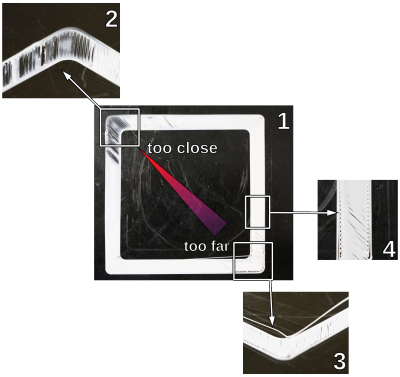
Accurate leveling is vitally important for the print result. Although correct first layer settings can compensate for slight unevennesses of the print bed, false leveling will ruin a print within the first few layers.
Evidence for a leveling mistake can be:
| No. | Appearance | Reason |
|---|---|---|
| 1 | Asymmetrical layer thickness, especially of the first layer. | lopsided leveling Appearance 2 and 3 are visible simultaneously |
| 2 | Smearing of the extrusion and possibly clogging of the nozzle. | Print bed and the nozzle are too close together. |
| 3 | The extruded strand is laid on the print bed instead of being spread. | Print bed and the nozzle are too far apart. (can be due to a wrong bed temperature also – better double-check) |
| Strands do not stick to the print bed but are being pulled away by the nozzle tip. | ||
| 4 | Extrusion of rounded, unjoined strands. | Print bed and the nozzle are too far apart. |
To avoid such irritations, make use of the following tips:
- Always make sure that the build chamber is adequately and uniformly preheated to at least 90 % of the target temperature (e.g. 63 °C for ABS).
The Z-end stop is temperature sensitive and may cause deviating positioning when exposed to temperature variations.
Keep the build chamber doors as shortly open as possible during leveling to avoid too much heat loss. - If you removed the print bed, always re-insert it in the same direction and orientation it had during leveling.
- Put the print bed with the convex side down onto the print table.
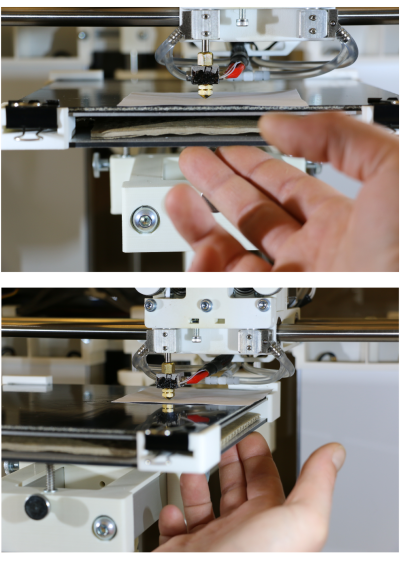
- After adjusting all three leveling points, return the print head to the first position (tap the [Back] button). Check the bed - tip distance by tapping (not pressing) the print bed with a finger next to the nozzle tip: if you see a gap appearing at the slightest touch, the leveling point is correctly adjusted. If even the least pressure is required, the leveling is too high. Repeat this at the other two leveling points. Have a look at the adjacent videos for visual explanation.
- Before waisting time on unsuccessful leveling, please rethink if the currently installed nozzle tip is adequate for the print job. Wider nozzles are more tolerant when it comes to compensating leveling mistakes and may be more suited to the task, especially when printing larger parts.
Tips for easier leveling
If you find it difficult to adjust the three leveling points uniformly with only the spring pressure, place a sheet of paper (not more than standard 80 g/m²) between the nozzle tip and the print bed and carefully push the bed against the tip before fastening the set screws. This way, you ensure a uniform bed - tip distance at all three leveling points.
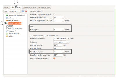
Another way of making leveling a little bit less important is “floating” your print on a raft. Slic3r (and most other slicing software) provides the “raft” function, a special kind of support material, which means that before starting with the actual object a (customizable) number of loosely printed layers is printed to compensate slight leveling mistakes. If you choose the raft settings correctly, beginning with a layer as wide and thick as allowable (depending on the nozzle tip's diameter) leveling will become a much less annoying process.
The raft's first layer is treated as the print's first layer and uses the respective settings. The following layers of the raft are calculated according to the support material settings. Choose the maximal first layer height (Slic3r → Print Settings → Layers and perimeters/First layer height) and a first layer extrusion width of 250 % (Slic3r → Print Settings → Advanced/Extrusion width -First layer) for a compensating, condoning and stable raft.
The raft can either be built of the model's material and cut away later or, if available for the specific plastic, of support material and broken off or dissolved. Check with the Materials' section to see if a secondary support material is available. For break-away or soluble rafts the dual extrusion function of the RepRap Industrial is required. Remember to check that all necessary calibrations and settings have been made as described above.
Deactivating the heating elements after end of print job
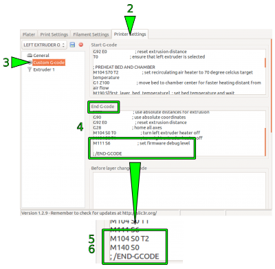
Sometimes you may want to start a print job just before finishing time or the weekend. Since there is currently no automatic shutdown function, the 3D printer will then stay on all night respectively some days. With the following description you can alter the End G-code of your print so that the heating elements are shut off after the print job has been finished so that the power consumption is reduced significantly. A side effect is, that due to the fact that the build chamber needs some hours to channel off the heat the cooling process is slowed and thereby internal tensions of the printed object are reduced. To deactivate the heating elements after a print job:
- Start your slicing software.
- Open the [Printer Settings] tab.
- Choose the “Custom G-code” menu.
- In the End G-Code editor scroll down to the end of the text field and position the cursor in the last line above the
; /END-GCODEentry. - Enter the command
M104 S0 T2
This will set the heating elements of the build chamber to a temperature of 0 °C. - Enter the command
M140 S0
This will deactivate the print bed as the last action of the current G-code.
Adjusting the build chamber temperature
NOTICE
The build chamber temperature is preset to the maximal permissible temperature of +70 °C at delivery.
Exceeding +70 °C will damage interior components of the RepRap Industrial such as stepper motors, bearings and electronics.
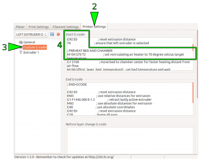
Since hitherto the RepRap Industrial is the only commercially available Open Source 3D printer with an actively heated build chamber, common slicing software does not feature ambient temperature settings. For some materials, it is advantageous to modify the chamber temperature together with the other temperature settings. The build chamber's temperature of the RepRap Industrial is set via the “Start G-code” which can be manually altered.
To change the build chamber temperature (in the following example we use our standard Slic3r - other software may differ in denotations):
- Open your slicing software.
- Open the tab [Printer Settings].
- Choose the Start G-code editor in the “Custom G-code” menu.
Scroll down to
; PREHEAT BED AND CHAMBER
and position the cursor in the line reading:
M104 S70 T2; set recirculating air heater to 70 degree celcius target temperature
- Change the entry “Sxy” (here S70) by replacing the value xy with the desired temperature, for example 50° C:
M104 S50 T2; set recirculating air heater to 50 degree celcius target temperature
(for logical reasons, the comment should be aligned).
- If you want to keep the settings, save them in a new profile (see Slic3r manual).
Any G-code exported with this profile loaded will heat the build chamber to the stated temperature prior to printing.
G-code manipulation at the GUI
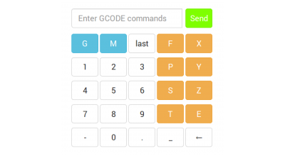
The following list contains supported G-code commands that can be used on demand to directly interfere with a print procedure or setting via the G-code keyboard of the GUI's Log menu.
| Command | Effect | Example |
|---|---|---|
G1 | Coordinated Movement X Y Z E | G1 X130 Y85 Z1.75 E4.35 |
G4 S<seconds> | Wait for given duration in seconds | G4 S5 (waits 5 seconds) |
G28 | Home all axes | |
G90 | Use absolute coordinates | |
G91 | Use relative coordinates | |
M80 | Activate build chamber | |
M82 | Set E codes absolute (default) | |
M83 | Set E codes relative while in Absolute Coordinates (G90) mode | |
M104 S<temp> T<extruder> | Set temperature without wait | Adjusting the build chamber temperature, Deactivating the heating elements after end of print job |
M109 S<temp> T<extruder> | Set temperature with wait | |
M140 S<temp> | Set bed target temp without wait | |
M190 S<temp> | Set bed target temp with wait | |
M221 S<extrusion flow multiplier in percent> | Increase/decrease given flow rate | M221 S95 → decrease flow to 95 % of g-code value |
M220 S<print speed multiplier in percent> | Increase/decrease print speed of all drive speeds | M220 S95 → decrease print speed to 95 % of g-code value |

