Table of Contents
Service guide for HT500
The instructions below are meant to enable you to perform troubleshooting, repair and cleaning tasks adequately and without damaging the machine.
Read the respective guide carefully before you start to work on the HT500 3D Printer.
In some cases you may need to lookup additional information for a specific task. Since we are trying to provide all necessary information independent from the hard- and software version of your actual HT500 you may have too choose from different sources.
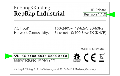
To find the valid hardware revision of your 3D Printer, check here.
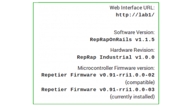
To find the valid software version of your 3D Printer, check here.
In case you are unsure about steps mentioned in this guide just ask for help any time - we will as always do our best to answer all questions that may arise.
Support requests - required information
In case you require support and contact us please always provide the following information:
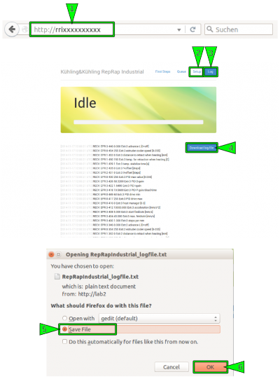
- The .log-file, downloaded via the web interface's Setup tab.
INFO
When downloading the .log-file via the web-interface, please open the Setup tab first so that the currently set EEPROM data are written into the log.
The log file saves all operating and communication commands since the initial commissioning and exports the last 10,000 commands into a data file. Due to this, it may require a few minutes for the system to gather all necessary data before the download menu appears.
- All system information provided on the Setup menu
(not valid for RepRapOnRails v1.0.5 or older).
Additionally, the following information may be helpful for examining and evaluating your specific request:
- Photos of unsuccessful prints often give a clue of what may have gone wrong.
- G-codes of above mentioned prints and the respective .stl-data allow for reprinting and reproducing your print job and help identifying faults.
- Photos and short videos of components, be they damaged or behaving oddly, always provide some clarification.
Packing and transport safeguarding
If the HT500 is to be shipped (e.g. for a full manufacturer's in-house inspection), it must be thoroughly packed and all moving components must be carefully secured against shifting to avoid transportation damages.
INFO
Replacement of parts damaged due to improper transport securing will be carried out at your costs.
Safeguarding of movable components
You will need the following material:
- removable strapping tape
(e.g. tesa® Strapping 64250, Scotch® Strapping Tape 8898 Blue) - packing foam foil
(any PE-foam for common packing applications) - cardboard
The following description assumes that:
- all axes are in their respective home position;
- filament has been unloaded and the 3D Printer has at least been briefly cleaned;
- the 3D Printer has been switched off, disconnected from the power supply and cooled down;
- all cables have been removed from the rear side.
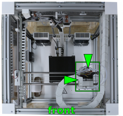
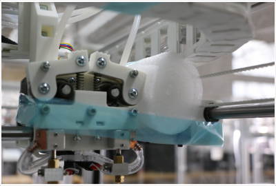
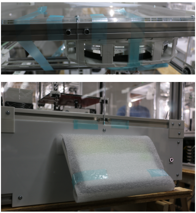
The first and most important component to be secured is the extruder head. It is mandatory to fix it exactly as shown here. Otherwise sensors and other components may be damaged beyond repair and must be replaced.
- Move the H-bridge to the front and the extruder head to the right-hand side.
- Place a foam coil between the extruder head and the right X-axis shaft carriage and push the extruder head against the coil.
- Fasten the extruder head together with the carriage by entwining them with strapping tape.
Make sure to tension the tape so that any extruder head movement is prevented.
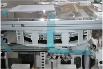
- Fasten the energy chain to the printer top cover.
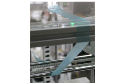
- Fix the H-bridge with strapping tape against forward movement by fastening it to one of the Z-Axes.
- Fix the H-bridge with strapping tape against backward movement by fastening it to the printer top cover.
Make sure to tension the tape to prevent forward/backward movement of the H-bridge.
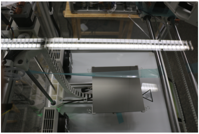
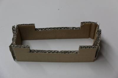
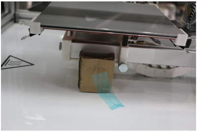
- Cut and prepare a cardboard support as depicted.
- Place the support underneath the print table and fix it with strapping tape.
Packing for transport
After safeguarding, the 3D Printer is ready for packing. You will need the following material:
- 4x lashing strap or tension belt
- closed surface transport pallet
- packing foam foil
- 4x anti-slip mats 50 x 50 mm (only 3D Printers without rubber feet)
- OSB transport top cover (or similar) 700 x 700 x 25 mm
- delivery transport box side cover frame
- delivery transport box lid
The description refers to using the original transport box the 3D Printer was delivered in. If you disposed of the box, make sure to provide adequate replacement.
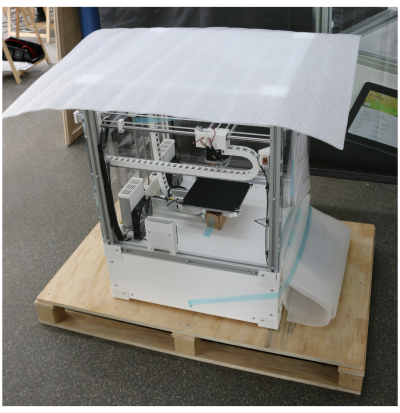
- Lift the 3D Printer onto the center of the pallet.
- Place a suitable piece of transport foam foil on top of the 3D Printer.
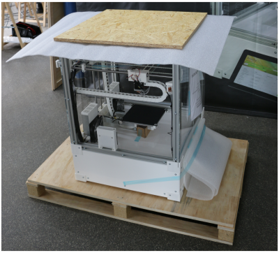
- Place the cover plate on top of the 3D Printer.
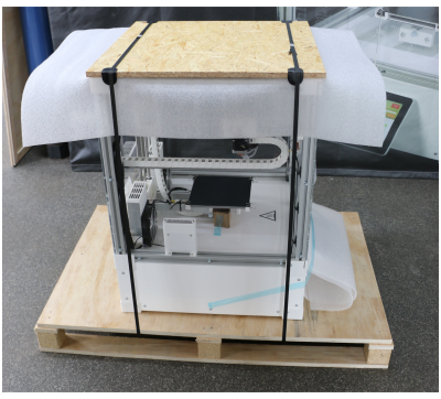
- Fasten the 3D Printer with two lashing straps to the pallet.
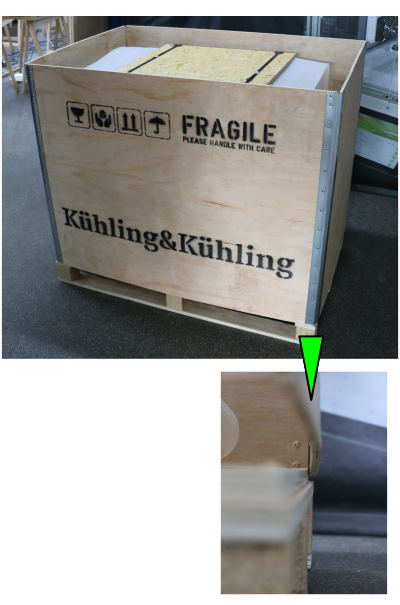
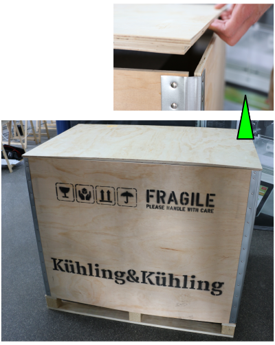
- Lift the side cover frame onto the pallet.
Make sure that the grove of the pallet fits smoothly.
- Close the box with the lid.
Make sure that the lid smoothly fits into the side cover frame.
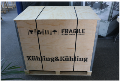
- Secure the transport box with two lashing straps on the pallet.
- Attach all necessary labeling on the outside:
- dispatch note
- UP sticker (present on the original transport box)
- FRAGILE sticker (present on the original transport box)
- PROTECT FROM WEATHER EFFECTS (if required, present on the original transport box)
Hardware components and manual tasks
Maintenance Intervals
Daily (end of shift)
| Where | What | Tools / To Do |
|---|---|---|
| Build chamber | - remove filament residues | brush, hand broom, vacuum cleaner |
Monthly (150 operating hours)
| Where | What | Tools / To Do |
|---|---|---|
| Timing belt | - check the tension; re-tension if required | Description |
| Shafts | - check for dryness; lubricate if required | Description |
| Cooling circuit | - check hoses for excessive bubbles; refill if required - check hose connectors at the LEDs and the stepper drives for correct positioning; refasten if required | Description |
| Dust wiping sponge | - check for cleanliness; clean or replace if required | rinse with fresh water and dry thoroughly |
Semiannually (1.250 operating hours)
| Where | What | Tools / To Do |
|---|---|---|
| Air filter | - exchange filling | Description |
Yearly (2.500 operating hours)
| Where | What | Tools / To Do |
|---|---|---|
| Z-axis spindle drive | - check for fast seat: with the 3D Printer switched on, grab the print table near the elevator and try to lift it → play of the table on the spindle requires replacement of the spindle nut → if you can lift the entire assembly including the spindle, the adjusting rings must be refastened | Description |
Cleaning recommendation
DANGER OF INJURY
Some plastics need very aggressive solvents that may cause intoxication, caustic burns, skin, eye and/or mucosal irritations, allergic reactions and other medical consequences. Solvents may emit flammable or toxic vapors or be corrosive.
To avoid injuries and accidents due to use of solvents:
- Always observe the safety information provided in the manufacturer's safety data sheet concerning possible dangers, handling and adequate storage.
- Always wear adequate protective equipment.
- Do not use solvents in a surrounding not suited to the task. If required, adequate aeration or exhaust ventilation has to be provided.
- Always use adequate containers for handling and storing solvents.
- It is the owner's responsibility to provide any necessary equipment and protective gear for every person operating the HT500 3D Printer.
DANGER OF BURNING
The build chamber interior may reach temperatures of up to 70 °C (158 F°), the print bed may reach temperatures up to 130 °C (266 °F) and the hot ends may reach temperatures up to 300 °C (572 °F). Touching components can cause burning injuries ranging from burn blisters to medium aching burns. Before cleaning any component inside the build chamber:
- Move the print head to the maintenance position (GUI → [Expert Control] → [Print Head Maintenance Position]).
- Switch preheating of the 3D Printer off (GUI → [Print] → [Preheat Chamber/Bed OFF]).
- Let the printer cool down to at least 52 °C.
NOTICE
Acetone is the most effective solvent for ABS and thus recommended for most cleaning purposes at the HT500 3D Printer.
To remove residues of other plastics than ABS, refer to the knowledge base or the respective manufacturer's data sheet for suitable solvents.
Regard the following when using solvents for cleaning purposes:
- Do not use solvents inside the build chamber. They may evaporate and produce fumes that can dissolve plastic components (e.g. the energy chain links) and printed objects. Always remove components from the build chamber before treating them with a solvent and dry thoroughly before re-insertion.
- Do not use liquids inside the build chamber. These may enter the electronic chamber and cause short circuits or otherwise damage electronic components.
Housing
Although during normal operation it is not necessary to clean the 3D Printer daily, regularly dusting reduces the probability of dust entering the feed system and causing clogging. Also, the visual appearance of the 3D Printer is improved and damaged components are more easily detected.
All components of the HT500s' housing can be cleaned with mild household detergents (e.g. dish soap, glass cleaner) and lint-free towels.
Do not use abrasive detergents or scouring pads as these will scratch and blind the acrylic glass covers and the touchscreen surface.
Material residues should be removed routinely from the build chamber. Use a soft brush or a low-running vacuum cleaner to remove loose material shreds.
Touchscreen
If required, use a microfiber or spectacle cloth moistened with glass cleaner to wipe the touchscreen.
Print bed
PEI is highly resistant to a lot of solvents. It is particular compatible with acetone and isopropyl alcohol.
If you experience insufficient adhesion of objects to the surface during prints, it is advisable to thoroughly clean the print bed with an acetone-soaked lint-free cloth.
Grease residues on the surface of the print bed (i.e. fingerprints) can lead to poor adhesion. To degrease, apply isopropylalcohol to a lint-free cloth and thoroughly wipe the surface. During further use, regular removal of grease residues with isopropyl alcohol will prevent poor adhesion.
Use acetone as solvent to remove ABS residues from the print bed. Apply the acetone to a cloth and wipe the print bed rather than dousing it directly.
Other material's residues are best removed with a lint-free towel soaked in a suitable, non-corrosive, non-toxic solvent. Observe the manufacturer's safety data sheet when handling plastic solvents. Make sure to thoroughly wash off any residues. Remaining smear may lead to increased adhesion, which can render it impossible to release printed objects without damage.
Hot ends
Cleaning the hot end nozzle tip is required quite often compared to other components of the 3D Printer. Dust ingression through the filament supply system, coking of material, and storage in a dusty place may lead to clogging of the tip's bore.
An imprecisely (too closely) leveled print bed, too low extrusion temperatures or too high an extrusion speed can lead to the nozzle tip choking itself.
In any of these cases, a decreasing print quality and slipping of the drive gear will be the first visible effects. Removing and cleaning the nozzle tip is then necessary; the description below should remedy the problem, as long as no hardware defect is present.
Cleaning the extruder hot end barrel is only required if it is clogged with coked material or foreign particles. It is recommended after dissembling the hot end at material change (installing a different material).
INFO
In areas with high dust formation, especially from textile fibers and similarly flexible particles, the risk of the nozzle tips to become clogged is highly increased.
Filament drive gear
Slipping of the drive gear is almost always the first and visible consequence of a clogged nozzle.
Other conditions (e.g. too high idler tension) may also cause the drive gear to grind into the filament and fill with abrasion. Material transport will stop and the print job will not be finished.
Regard that the printer will nevertheless continue to print if not aborted by the operator.
Clean according to the description below.
Remedying clogging
Required tools
- dental pick hook or needle
- material specific solvent
- pipe cleaner
Additional information
Procedure
To clean a nozzle tip:
- Screw off the nozzle tip.
- Roughly remove material residues mechanically (e.g. using a brass wire brush - wear protective goggles!).
- Drop the nozzle tip into a suitable solvent and wait for the residues to be loosened or completely dissolved.
- Remove remaining material mechanically.
- Dry the nozzle tip thoroughly before re-installation.
To clean the inner bore of the extruder barrel:
- Dissemble the hot end as described.
- Run a pipe cleaner through the barrel's bore to remove loose particles.
- Dissolve any residues in a suitable solvent.
- Remove remaining material mechanically.
- Dry the barrel thoroughly before re-installation.
To remove particles and abrasion from the feed system:
- Remove the filament strand from the supply system.
- Take out the dust wiping sponge from the filament inlet, rinse it with water, and dry it thoroughly.
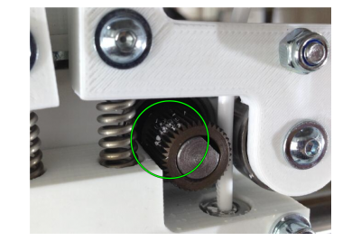
- Scrape the teeth of the drive gears with a pointed tool (e.g. dental pick).
- Reinstall the supply hoses and the dust wiping sponge.
Completion
After having re-installed or exchanged all components, reload the filament and run the [Prime Extruders], and the [Print bed leveling] wizard.
Shaft lubrication
All slide bearings of the HT500 are equipped with dry-run linear slide bearings. Nonetheless, the shafts may accumulate dirt or condensation which may lead to stick-and-slip effects on the bearings, especially at the Z-axis. Slightly Lubricating/Cleaning the shafts may then be necessary.
Required tools
- Ballistol Universal (manufacturer's website (DE))
- paper towel or lint-free cloth
NOTICE
Do not use any other lubricant. The dry-run slide bearings are sensitive to oils and fats and may get irreparably damaged when greased falsely.
Applying lubricant
If you notice strong vibrations of the print table during homing and leveling or if your printed objects show increasingly rough vertical irregularities:
- Apply Ballistol Universal to a paper towel.
- Coat the shafts with a thin layer of the lubricant.
- Wipe off excessive lubricant.
INFO
During preheating, the freshly applied Ballistol Universal will emit a smell that you might find offending.
This is not harmful and will wear off in a couple of hours.
Opening the electronic chamber
To access the cooling system or the control elements, you have to remove the left or the right side cover panel. The description below applies to either side.
ELECTRIC SHOCK HAZARD!
Electric shock can cause severe injuries. Never open the electronic chamber when the 3D Printer is powered on.
Always shut down and power off the 3D Printer and disconnect the power supply before removing covers and working on electronic components. Allow the power supply to discharge for at least one minute.
NOTICE
Electrostatic discharge can damage electronic components. Ground yourself before touching electronics.
Required tools
- Allen wrench #2.5
Additional information
Removing
Shut down the printer via the touchscreen panel, switch off the main power switch and unplug the supply cable. Open the electronic chamber of the 3D Printer in the following sequence:
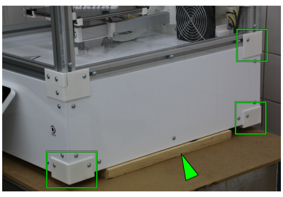
- Slightly tilt the apparatus to the opposing side and place a square length of wood underneath the bottom.
DANGER OF CRUSHING!
Capsizing of the 3D Printer can cause crushing injuries and damage the housing beyond repair. Make sure the apparatus does not topple.
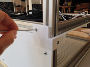
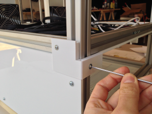
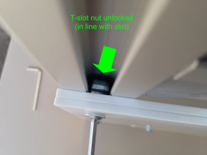
- Loosen (do not remove) the hexagon socket screws of the feet and the upper hind cover angle.
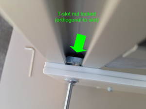
- Turn the hammerhead nuts by 90°.
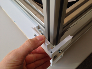
- Remove the feet and the angle.
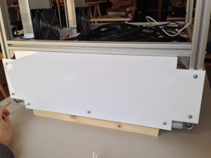
- Loosen (do not remove) the hexagon socket screws of the cover panel.
- Turn the hammerhead nuts by 90°.
- Remove the cover panel.
- Loosen all screws around the white acrylic side panel and take the panel off. You now have access to the electronics driving the HT500.
Reinstall in reverse order, remove the wood and restart.
Changing the nozzle tip
Printing with another nozzle diameter, cleaning or change of material all requires unscrewing and remounting the nozzle tip. Although not a complicated procedure, make sure to read the following description thoroughly to avoid damaging the hot-end.
BURNING HAZARD!
Before unscrewing a nozzle, the filament must be removed from the hot-end which may require heating to extrusion temperature. Depending on the installed material temperatures up to 300 °C may be necessary that can cause severe burns.
- Be careful not to touch hot components.
- After loosening the nozzle let the extruder cool down before starting to work on it.
Required tools
- open-jaw wrench size 8
- open-jaw wrench size 4
Additional information
Removing the nozzle tip
After the extruder has cooled down:
- Open the Expert Control menu, tap the [Printhead Maintenance Position] button and wait until the print head has moved to the middle front position.
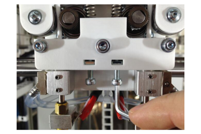
- Loosen the barrel set screw at the hot end mount.
NOTICE
Do not loosen the nozzle tip without loosening the barrel set screw and countering the barrel. Distorting the barrel may damage it. The barrel must then be replaced.
If solidified material hinders loosening the nozzle tip effortlessly, heat up the extruder to the specific extrusion temperature and loosen the tip 2 or 3 turns. Do not unscrew the heated tip totally. Dropping the hot nozzle tip will damage the acrylic bottom.
Afterwards, turn the extruder off and wait until it has cooled down before completely removing the nozzle.
- Loosen and remove the nozzle tip with a size 8 wrench while countering with a size 4 wrench at the width flat of the barrel.
Installing a new nozzle tip
- Screw the nozzle tip onto the melter thread.
NOTICE
Overtightening the nozzle tip may shear off the thread.
Do not fasten the nozzle tip without countering.
- Carefully fasten the nozzle tip with a size 8 wrench while countering with another size 8 wrench at the melter.
- Run the Print Bed Leveling wizard.
INFO
Prior to installation clean the nozzle tip with acetone or isopropyl alcohol to remove any dust, oil, shavings, etc., and dry it thoroughly.
Clean removed nozzle tips adequately and store them in a dry, dust-free box.
Changing the hot-end barrels
For cleaning purposes, when changing the print material or in some problem cases you have to remove and replace a hot-end barrel.
Required tools
- Allen wrench #1.5
- tongs (optional)
Additional information
- Software manual: filament change
- Troubleshooting: P1
Deinstalling the barrel
- Remove the nozzle tip as described above.
- With the set screw loosened, carefully push the barrel to the limit up the nozzle seat.
- Fixate the barrel by fastening the set screw.
- Carefully pull the heating block off the barrel and let it dangle at its cables.
Installing a new barrel
Install the left extruder nozzle first:
- Carefully push the barrel to the limit up the hot-end mount and fixate it by fastening the set screw.
- Slip the heating block onto the barrel.
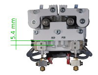
- Loosen the set screw and lower the barrel until its upper end is level with the hot-end mount's upper rim.
- Fasten the set screw.
- Install the right extruder nozzle in the given order but a little above the left hot-end.
- Run the Print Bed Leveling wizard.
- Run the Calibrate Extruder Offset wizard.
Refilling the cooling circuit
Temperature fluctuation cannot be avoided due to the operating conditions of the HT500. The different thermal expansion of the materials causes minimal leakage at the cooling circuit's connections which makes refilling the circuit necessary approximately every four weeks. To refill the coolant circuit, follow the instructions given below.
Required tools
- Coolant Innovatek Protect IP ready-to-use ¹ (max. 250 ml)
- Allen wrench #2.5
¹ Order directly via sales@kuehlingkuehling.de, the manufacturer's webshop (http://innovatek.de, manufacturer part number: 500473) or related distributors.
Checking the cooling circuit
NOTICE
Lack of coolant may lead to damage of the affected components, especially the LEDs. Too much air in the cooling circuit leads to clogging of the copper connectors due to oxidation.
Check the cooling circuit regularly for excess amounts of gas bubbles.
The amount of gas bubbles in the cooling circuit is the indicator for refilling. A small amount of bubbles always circles the hoses and can be considered normal. To asses whether the cooling circuit must be refilled, check the following:
- The bubbles are small and running freely → there is no need for refilling the cooling circuit.
- Bubbles reach the size of the hose's diameter, are sticking in places and do not disappear a few minutes after switching the build chamber on → refill as described below.
Demounting and refilling the pump
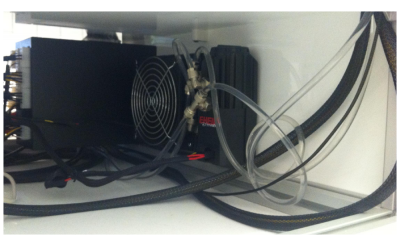
If you need to access the cooling water pump (e.g. for refilling coolant), you first have to remove the right-hand side cover of the electronic chamber. Then:
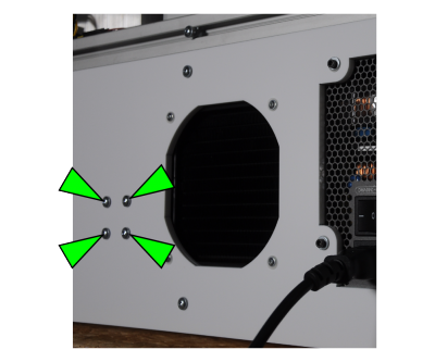
- Unscrew the four holding screws on the left side of the cooling unit radiator grill at the rear cover.
- Pull the pump out of the chamber. The hoses' lengths are designed for this.
- Remove the pump's lid by turning it counterclockwise and pulling it off.
- Refill with coolant up to the level indication.
- Let the pump run for some minutes. Monitor the coolant hoses and check that air bubbles run freely. If necessary, carefully flick the hoses to free trapped air. When all air bubbles have left the cooling system, check the filling level of the pump again and refill to the upper limit.
- Press the lid into the housing and turn it clockwise. Make sure the lid is positioned fast in its seat and locked.
- Reinstall the pump at the rear cover and close the electronic chamber.
Air filter
Required tools
- Allen wrench #3
- activated charcoal granules (∅4 mm, 10 g)
Refilling the charcoal container
Exchange the activated charcoal of the air filter every six month:
- Switch the 3D Printer off and let it cool down.
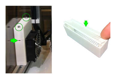
- Unscrew the two screws of the container with a cross-tip screwdriver and take it of.
- Open the lid of the container (press down at one side) and dispose of the used up granules.
- Refill with fresh charcoal granules.
- Close and reinstall the container. Make sure that the square nuts are in place when fastening the screws.
Extruder idler lever
Required tools
- Allen wrench #3
Adjusting the preload
At delivery, the idler lever preload is preset to work with the standard material Kühlung&Kühling ABS snow-white. To print other plastics it may be necessary to adjust or readjust the tension of the idler lever spring.
Too high tension of the idler lever spring may result in the gear drive to slip and grind into the filament. Too low tension of the idler lever spring may result in slipping of the gear drive. In both cases the print will abort due to insufficient material transport.
Adjust the idler lever spring pressure by turning the tensioning screw with a metric #3 Allen key, just enough that the filament is transported reliably without slipping or chipping. Turn the screw clockwise to increase the preload and counterclockwise to decrease it.
To test material transport efficiency run the Prime Extruders wizard and readjust if necessary.
INFO
Be gentle, too much pressure is counterproductive and will result in chipping filament.
Timing Belt Tension
The Tension of the X-axis and both Y-axis timing belts can be checked by measuring the resonance frequency when plucked like a guitar string.
- Activate the build chamber preheating and wait until the 3D Printer has reached its operating temperature (70 °C for printing ABS).
- Then pluck the longest free hanging section of a belt and measure the oscillation with a frequency meter.
Make sure to be as close to the belt as possible with the microphone of your device. - Adjust by rotating the knurled thumb-wheels on each belt tensioner until a frequency of about 60 Hz (+/-5 Hz) is met.
- Repeat this procedure for all belts.
Repositioning and refastening the Z-axis clamp collar
During transport or set up verberation may lead to loosening of set screws. If this happens at the upper clamp collar of the Z-spindle, the initial Z-positioning of a print job becomes inaccurate although the leveling seems OK because the spindle's mechanical backlash will then avert exact positioning only during minimal lifting moves. You will find that the first layer will not stick to the print bed as if it was leveled too high.
In this case the clamp collar must be repositioned and the set screw must be refastened.
Required tools
- Allen key #2.5
Testing and repositioning the clamp collars
DANGER OF BURNING!
Depending on the printed material components of the 3D Printer may hold temperatures up to 300°C (572°F) immediately after a print job.
To avoid burning injuries:
- Switch off the preheating and wait until the 3D Printer has cooled down to approximately 50°C (122°F).
- Check the current temperature at the display.
NOTICE
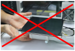 Lifting the print table at the front end may damage the Z-elevator assembly and the spindle. Also, leverage effects might effect a false impression of alleged play.
Grab the print table at the Z-elevator near the bearings when trying to lift it.
Make sure that you do not damage the Z-limit switch.
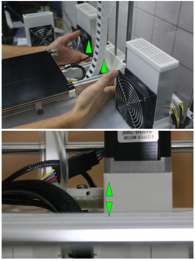
To test if the clamp collar has come loose, carefully try to lift the print table and observe the Z-drive pulley.
If the pulleys moves up and down, the clamp collar must be repositioned and the set screws refastened.
To reposition the clamp collar:
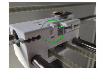
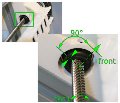
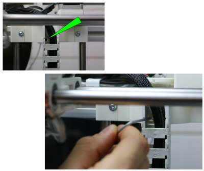
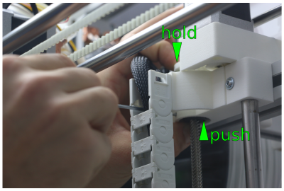
- Carefully turn the spindle of the Z-drive manually so that the recess of the clamp collar points left.
- Loosen the set screw through the access bore in the carriage.
Electronic components, software and slicing
Download latest Slic3r Configuration Profiles
To allow for always up-to-date Slic3r configuration profiles, the provided config-files were removed from the touchscreen controller system into a separate online repository. As shown on the “First Steps” tab of the web interface, these can now be downloaded from https://github.com/kuehlingkuehling/RepRap-Industrial-Slic3r-profiles/releases in their latest version.
Exchanging the UDOO SD card
In case an update of the operating system, the touchscreen or the firmware is required, Kühling&Kühling offer update files at http://docs.kuehlingkuehling.de/. Subscribers will be informed via newsletter, for all other users we recommend to regularly check the blog (http://kuehlingkuehling.de/) or the documentation for updates.
The Micro-SD card in the UDOO always contains all data necessary to run the operating system as a stand-alone unit, which means that you do not have to overwrite the current operating system but can use a second SD card to replace the original one. This is for safety reasons if something should go wrong during the updating process and you need to quickly restore a functional system.
Updating procedure
- Finish all print jobs and turn the operating system off via the touchscreen ([Shut-down] button).
- Let the 3D Printer cool down.
- Toggle the main switch at the back off the apparatus to <0> (OFF) and remove the power supply cable.
- Remove the left side cover of the electronics enclosure (removal procedure as described here).
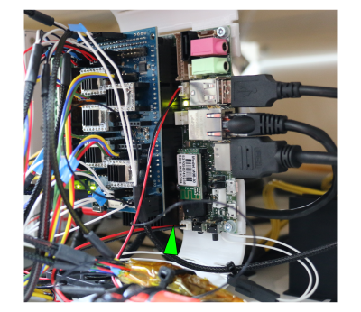
- Carefully remove the SD card deeper from its slot at the lower edge of the UDOO board. The card is positioned behind the dissipator and has a “push and release” removal mechanism.
- Insert the new SD card into the slot.
- Reinstall the side cover of the electronic enclosure.
- Plug in the power supply cable.
- Switch the 3D Printer on by toggling the main switch to <I> (ON).
After the start-up sequence has finished, the HT500 is now running with the updated operating system.

