Table of Contents
Software version v1.0.5 - Operation and commissioning
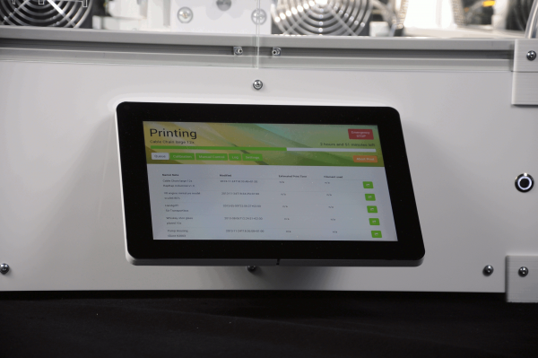
This manual describes the operation of the RepRap Industrial via the operating software RepRapOnRails version v1.0.5 and the initial commissioning of the 3D printer after installation.
Operation
The following paragraphs provide an overview of the operating screens of the touchscreen and explain the specific buttons valid for RepRapOnRails software version v1.0.5. Additional information on the print preparation can be found in the tips and tricks category and the manual of the slicing software.
Queue
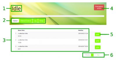
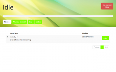
Queue is the are basic overview screen about the print jobs having been sent to the 3D printer and waiting to be processed. After starting the 3D printer the screen will appear as the start-up screen where you can select and start print jobs.
| No. | Description | Content/Function |
|---|---|---|
| 1 | Status message | Idle: apparatus is waiting for next user input |
| Printing: apparatus is busy printing workpiece | ||
| 2 | Menu buttons | Select the operating menu and mode: |
| Queue represents the main production mode | ||
| Manual Control provides access to motors and temperature control | ||
| Log represents the communication history of microcontroller, BeagleBone Black, and touchscreen | ||
| Setup provides wizards for different preset operating procedures | ||
| 3 | Print job list | list of uploaded print jobs sorted by time/date (oldest first) |
| 4 | [Emergency STOP] button | see safety information |
| 5 | [print] button | Push to start the respective print job. |
| 6 | Browse buttons | Use [Previous], [Next] and [page number] to browse the print job list. |
Printing
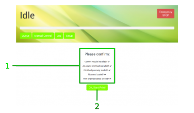
After pushing the [print] button next to a print job in the list you will be asked if all preparations for the print job have been performed.
| No. | Description | Content/Function |
|---|---|---|
| 1 | Checklist | Please check the listed points before proceeding. |
| 2 | [OK, Start Print] button | If all preparations have been made, tap to proceed. |
After confirmation the RepRap Industrial starts processing the print job and the status message changes to Printing. All other menus are deactivated during a print. The print job name, the current progress, and the estimated remaining time are displayed and the [Abort Print] button is active.
| No. | Description | Content/Function |
|---|---|---|
| 3 | Print job name | The name of the slicing file uploaded to the queue. |
| 4 | Countdown | Displays the estimated remaining time (calculated from the G-code). |
| 5 | Progress bar | Indicates the progress of the print job graphically. |
| 6 | [Abort Print] button | Push for anytime abortion of a print job. |
| 7 | [Pause Print] button | experimental |
Aborting a print job
If you wish to abort a print job, because the outcome does not meet expectations for example or mechanical problems appear during the print, push the [Abort Print] button. The system will then print the last G-code information from cash and move the print table and the extruder head to their home positions afterwards. The heating resistors are switched off so that the build chamber and the print table cool down and you can remove the print bed.
DANGER OF BURNING!
The print bed and the extruder nozzles may still be too hot to touch. Be careful not to burn yourself when removing the print bed.
Experimental pause function
The [Pause Print] button is still in an experimental state. Right now, its function of interrupting and reliably continuing a print job does not meet expectations. Since up to date we have not found need of a pause functionality, this feature may well disappear with next software update.
Print job finished
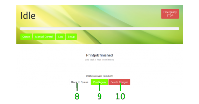
If either a print job has been completed regularly or aborted by the operator, the 3D printer returns to Idle mode and the screen will display a status message and a request how you wish to continue. Simply tap the respective button on the screen to proceed.
Manual Control
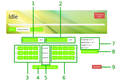
For maintenance and test reasons, after a crash or to reduce lead times, e.g. if you still need to work on a print file but want the 3D printer to be ready for operation, manually moving the motors or preheating the build chamber and the print table may be necessary or advantageous.
| No. | Description | Content/Function |
|---|---|---|
| 1 | [Build Chamber ON] / [OFF] | Activates/deactivates the entire build chamber functions. Tap in order to move the motors. |
| 2 | [Preheat Chamber/Bed ON] / [OFF] | Activates/deactivates the heating systems. Tap and wait, before proceeding. |
| 3 | Motor control - negative direction | Moves every axis individually once for every tap in negative direction, according to the selected step width. |
| 4 | [Printhead Maintenance Position] | Tap to move the extruder head into a preset position in the upper center of the build chamber directly in front of the doors where it is easily accessible for maintenance purposes. |
| 5 | Homing buttons | Tap to separately or simultaneously move the axes to their starting positions. |
| 6 | Motor control - positive direction | Moves every axis individually once for every tap in positive direction, according to the selected step width. |
| 7 | Temperature indicator | Displays the temperature of both extruder nozzles, the print table and the build chamber. While extruder nozzle and print bed temperatures are set directly in the slicing software, the chamber temperature must be defined via the Start G-code intentionally. |
| 8 | [Refresh Temperature] | Tap to actualize the temperature values in [7]. |
| 9 | [Shutdown] | Tap to switch the 3D printer into sleep mode. |
NOTICE
The positions of the extruder head and the print table are not compared during manual operation. Be careful not to crash the print table and the extruder head.
Log
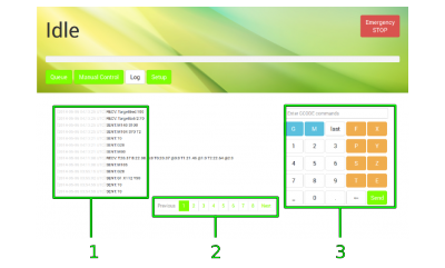
All communication between touchscreen, BeagleBone Black and microcontroller is stored and displayed on the log screen. Print job status are stored also.
Direct G-code programming can be effected via the G-code input field.
| No. | Description | Content/Function |
|---|---|---|
| 1 | History list | communication history sorted top down by date and time¹ SENT: BeagleBone Black to microcontroller RECV: microcontroller to BeagleBone Black |
| 2 | Browse buttons | Use [Previous], [Next] and [page number] to browse the history. |
| 3 | G-code input field | Enter G-code lines here and [Send] them. |
¹ The time is stated in universal time coordinated (UTC) notation so do not wonder if it does not match your local time.
NOTICE
The G-code input field is an advanced feature and requires sound knowledge of G-code programming. Operating the 3D printer via G-code input can lead to massive damage of the apparatus.
Setup
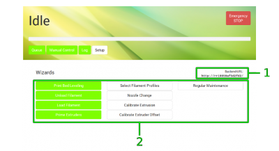
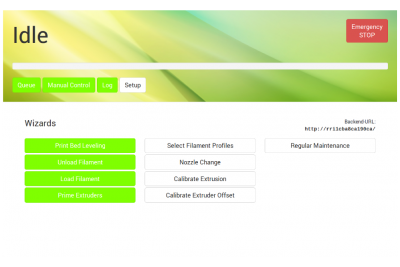
The setup menu displays walkthrough instructions (wizards) for different operations needed during production, initial commissioning, servicing and troubleshooting. If you choose one of the options, a step-by-step guide will provide all necessary information for completing the respective task.
| No. | Description | Content/Function |
|---|---|---|
| 1 | Backend URL | Needed to connect to your RepRap Industrial via your network (see below) |
| 2 | Wizard selection | Different wizards for different tasks; needed to keep your 3D printer up and running: |
| Print Bed Leveling: Ensure that the print bed has the same distance to the nozzle at every point. | ||
| Unload Filament: Wrong removal of filament from the supply can damage the machine. Follow these instructions when filament must be removed. Also regard the instructions below. | ||
| Load Filament: Wrong insertion of filament can damage the machine. Follow these instructions when filament must be refilled or changed. Also regard the instructions below. | ||
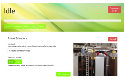
| Prime Extruders: After removing/refilling filament or subsequent to nozzle change the extruders must be primed to remove enclosed air from the nozzle tip. Also regard the instructions below. | ||
| Select Filament Profiles: Choose from preset, material specific profiles fitting the kind of filament you have loaded. To create filament profiles via the web interface see below. | ||
| Nozzle Change: If you need to change the nozzle tips (e.g. for printing wider or narrower extrusion width), follow these instructions. | ||
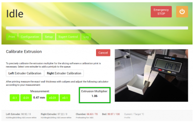
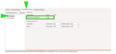
| Calibrate Extrusion: when printing material with other properties than before, it might be necessary to adjust the throughflow of the nozzle. To find the correct Extrusion multiplier to be entered in the Filament settings of Slic3r, run this wizard. | ||
| Calibrate Extruder Offset: this function is needed for dual extruder prints. To teach the offset distance between the nozzle tips in X- and Y-direction, run this wizard. | ||
| Regular Maintenance: This function will guide you through a set of maintenance measures that should be performed on a regular basis. |
Creating material profiles via the web interface
During a print job all necessary temperature data are provided by the respective G-code. For priming the extruders outside a print job the temperature setting required for extruding a material is provided by the Filament profiles.
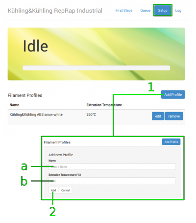
To create a filament profile open the web interface of your 3D printer, choose the Setup menu and:
- Select Filament Profiles and click [Add Profile] to set material properties.
- Enter the material Name in the according input field.
- Enter the Extrusion Temperature in °C in the according input field.
- Click [Add] or press <Enter> to save the settings. The new filament profile is added to the list, newest at the bottom.
- To change the settings click [edit] and enter the new properties.
- To delete a profile click [remove] and confirm the safety query.
Changing the filament
When the filament limit switch at the filament supply registers the end of the filament strand on the spool, the 3D printer stops automatically and signals lack of material at the touchscreen.
If you want to remove the filament for other reasons (e.g. to use a differently colored material), the following description applies also.
Required tools
- diagonal cutters
Refilling
If you want to continue printing with the same type of plastic, the change of the filament spool is quite easy. You have to manually remove remaining filament from the supply hose, change and, if need be, adjust the spool carriers and insert the new strand.
- Go to the Setup menu and start the [Unload Filament] wizard and follow the on-screen instructions.
- Open the Setup menu again, and follow the [Load Filament] wizard.
Material change
If you want to continue printing with another type of plastic (e.g. PETG instead of ABS), the change of the filament spool becomes a little bit more complex since you have to change the extruder nozzle barrel also.
INFO
Using the same extruder nozzle barrel for materials with different properties may lead to clogging of the nozzle tip due to coking or sooting.
Kühling&Kühling recommend either thorough cleaning of the extruder nozzle barrel with a suitable solvent and pipe cleaners or using a single barrel for every type of material.
INFO
Make sure to choose the appropriate filament profile from the material database. If you have not installed the adequate profile yet, do so by following the instructions given below.
Adjusting the spool carriers
Required tools
- Allen wrench #2.5
Procedure
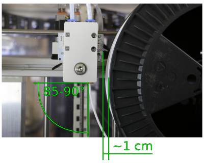
If you want to use a different filament spool diameter (less or more material), you have to adjust the spool carrier position.
INFO
With an appropriate Allen key you can carry out the following steps without removing the filament spool.
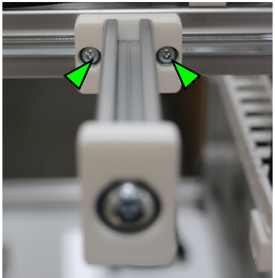
- Use the Allen key to loosen the fixing screws of the carrier.
Initial commissioning
After installation the RepRap Industrial is ready for initial commissioning. The first few steps will prepare your RepRap Industrial for its day-to-day duty:
- Make sure that no foreign objects are left in the build chamber (transport locks, tools or the like).
- Close the build chamber.
- Toggle the main switch to <I> (ON). When the power supply is switched on for the first time after connecting the power cord to the mains power, the 3D printer will boot up automatically. Please wait patiently until the full controller interface is loaded on the touchscreen at the machine front. The screen will show the Queue menu and the top-left status message should read Idle.
Preheating and leveling
The next step is preheating the build chamber and the print bed in order to enable calibration at operating temperature:
- Tap [Manual Control] to enter the respective menu.
- Activate the build chamber by tapping [Build Chamber ON] and then start the heating by tapping [Preheat Chamber/Bed ON]. The current temperatures are indicated on the right side of the screen. You can always check the temperature by tapping [Refresh temperatures].
- Let the build chamber heat for approximately 45 minutes.
After the preheating, it is necessary to calibrate the print bed in the given order.
- Tap [Setup] to change to the Setup menu.
- Tap [Print Bed Leveling] to start the wizard that will guide you through the leveling process.
- Follow the on-screen instructions step by step.
When the calibration has successfully been finished, all that is left is to load your RepRap Industrial:
- Tap [Load Filament] to start the wizard that will guide you through the material feed process.
- Follow the on-screen instructions step by step.
- At the end of the Load Filament wizard, follow the suggestion to run the Prime Extruders wizard by tapping the respective button.
INFO
Load the 3D printer with the Kühling&Kühling white ABS included in the delivery for the first print.
For priming the extruders, the correct material profile must be chosen. Creating temperature profiles is carried out via the web interface as described here.
To check or alter the settings, proceed as follows:
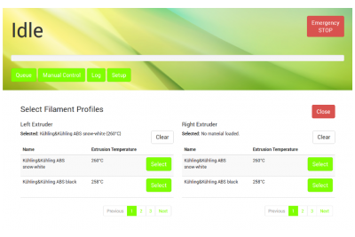
The material profile for each extruder is chosen via the [Select Filament Profile] button in the Setup menu.
Here you will find a list of material profiles consisting of the material name and the respective extrusion temperature.
Tap [Select] to choose a material and then [Close] to return to the Setup menu.
Extruder calibration
The extrusion properties of any material, although chemically exactly the same, may differ from one filament spool to the other so that it is impossible to determine the correct extrusion multiplier (see Slic3r manual) prior to delivery. After leveling the print bed, it is therefore mandatory to calibrate the extrusion to adapt your printer to the installed filament for ensuring a correct printing performance.
INFO
When printing ABS it may be necessary to run the [Extrusion calibration] wizard after changing the filament spool without changing the material itself.
It is necessary to find the correct extrusion multiplier after changing the material. The respective procedure is described here.
To calibrate the extrusion:
At the 3D printer
- Choose the [Calibrate Extrusion] wizard from the Setup menu at the touchscreen (see above).
- Select the respective extruder.
- Select and start the print job from the Queue.
- After the print job has been finished, return to the [Extrusion Calibration] wizard.
- Enter the measured value via the touch buttons.
- The necessary extrusion multiplier is calculated automatically. Take a note of the value and record it in the slicing software.
The first print
You will find all necessary installation and setup procedures required for the first print in the following paragraphs. The software mentioned additionally is available “Open Source” and is recommended for use with the RepRap Industrial since it has been thoroughly tested. Other software may be available but has not been tested.
INFO
The manufacturer cannot be held liable for any malfunction resulting from use of other than the recommended software.
Installation and setup of the slicing software
First you need to install a slicing software on your computer to translate .stl-files into printable G-codes.
Kühling&Kühling recommend using the Slic3r slicing software to prepare your digital 3D models for printing.
To prepare for printing follow these steps:
- Open http://slic3r.org/download and download the latest Slic3r installation package for your operating system.
Follow the installation instructions available at http://manual.slic3r.org/GettingSlic3r.html#installing. - Open https://github.com/kuehlingkuehling/RepRap-Industrial-Slic3r-profiles/releases and download the latest preconfigured Slic3r profiles package for the RepRap Industrial to your computer. Unpack the archive.
- In Slic3r go to File > Load Config Bundle and select the previously downloaded .ini file. Refer to the README file provided with the profiles for a description of the different profiles available.
INFO
When importing this profile bundle into Slic3r, existing presets may be overwritten. It is recommended to backup your custom/modified presets by exporting them as a bundle first (File > Export Config Bundle).
Preparing the 3D model
The 3D model you want to print must be available as .stl-file (stereolitographic data). Most common 3D modeling software is able to create this file format.
- Start Slic3r to process a 3D model into G-code data.
- Select the preconfigured profiles for filament, print and printer before generating a G-code file.
- Export the G-code data.
Refer to the Slic3r manual for help on fine tuning any parameters for the printing process.
Uploading print jobs to the 3D printer
Every PC connected to your network can access the RepRap Industrial via the network address that is displayed in the Setup menu at the GUI (“Backend-URL”).
- Open your internet browser and enter the URL in the address line.
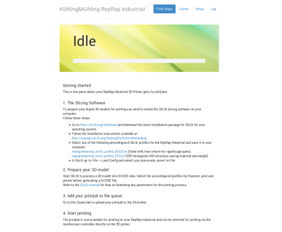
- The web-interface opens with the “First Steps” guide that also provides the information given in this chapter.
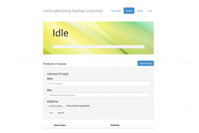
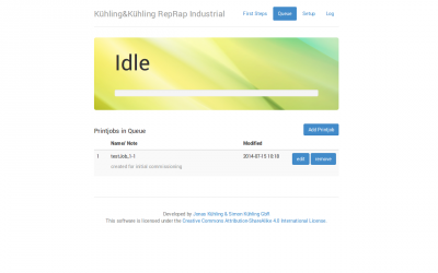
- Change to the Queue tab to upload your print job to the 3D printer.
- Click [Add Printjob] and then [Browse] to select a G-code.
- Enter the identification (name or number or the like) of the print job in the text field Name and if required add additional information via the text field Note.
- Click [Add] to upload the selected file to the printer.
The print job is now available for printing on your RepRap Industrial and can be selected for printing via the touchscreen controller directly on the 3D printer.
Starting the print job
Make sure that all previously described steps have been carried out.
The next steps are carried out at the 3D printer's GUI:
- Tap the [print] button on the Queue screen to start the print job.
- Wait until the apparatus has finished the print job completely and all axes are in their home position, then remove the print bed, take off the test object and check whether all expectations have been met.
- If everything has been fault-free, delete the print job from the queue - you are ready to proceed to production.

